
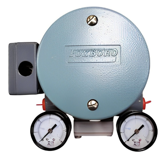
The E69F Current-to-Pneumatic Signal Converter (Figure 1) is a field-mounted instrument that transforms a dc milliampere input signal to a proportional pneumatic output signal.
This output signal can be used either to operate such pneumatic devices as dampers, and valve actuators, and so forth, or as the input to various pneumatic instruments.
FOXBORO E69F-BI2-S Current Pneumatic Signal Converter
Introduction
General Description
The E69F Current-to-Pneumatic Signal Converter (Figure 1) is a field-mounted instrument that transforms a dc milliampere input signal to a proportional pneumatic output signal.
This output signal can be used either to operate such pneumatic devices as dampers, and valve actuators, and so forth, or as the input to various pneumatic instruments.
Principle of Operation
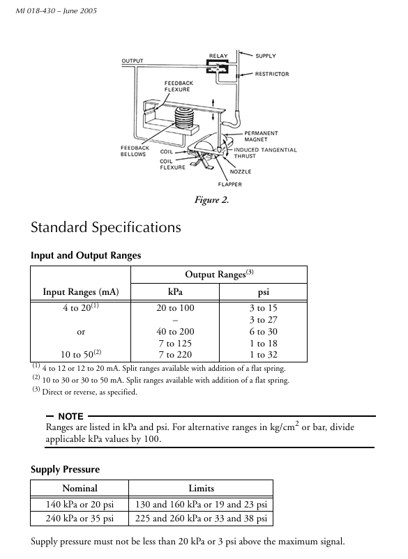
A dc milliampere input signal is converted to a proportional pneumatic output signal in the fol lowing manner (see Figure 2). A coil positioned in the field of a permanent magnet reacts to the current by producing a tangential thrust proportional to the input signal flowing through it. The thrust, acting through coil flexures, varies the gap between a flapper and a nozzle. This causes a change in the output pressure of the relay, which is also the converter output pressure. This pres sure is fed to a feedback bellows which exerts a force on a feedback flexure to move the nozzle and establish a throttling relationship between the flapper and the nozzle.
Input Resistance
4 to 20 mA Input: 170 Ω
10 to 50 mA Input: 27 Ω
Air Consumption
20 to 100 kPa or 3 to 15 psi output:
40G Relay: 0.5 m3/h (0.30 cfm) at standard conditions.
All other outputs: 40D Relay:
1.3 m3/h (0.75 cfm) at standard conditions with 140 kPa or 20 psi supply.
1.7 m3/h (1.0 cfm) at standard conditions with 240 kPa or 35 psi supply.
Ambient Temperature Limits
Normal Operating Conditions:
-30 and +60°C (-20 and +140°F)
Operative Limits: -40 and +80°C (-40 and +180°F)
Calibrated Accuracy
±0.5% of span; but ±2% of span with output signals of 7 to 125 and 7 to 220 kPa or 1 to 18 and 1 to 32 psi
Mass (Approximate) 2.3 kg (5 lb)
Product Safety
For electrical classification of converter, refer to data plate. For conditions of certification, refer to Table 1.
Calibration
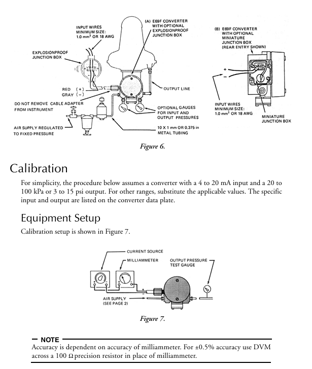
For simplicity, the procedure below assumes a converter with a 4 to 20 mA input and a 20 to 100 kPa or 3 to 15 psi output. For other ranges, substitute the applicable values. The specific input and output are listed on the converter data plate.
Procedure
NOTE Any adjustment to the span will interact with the zero adjustment and will change the initial zero setting. Therefore, any adjustment made to the span must be followed by readjustment of zero.
Set up equipment as shown in Figure 7.
Apply 12 mA (50%) input to converter and adjust output (zero screw) to 60 kPa or 9 psi (50%). See Figure 8.
Apply 20 mA (100%) input to converter and note amount of error above or below 100 kPa or 15 psi (100%) output. If error is greater than ±2% (1.6 kPa or 0.025 psi), perform Step 4. If error is less than ±2%, proceed to Step 5.
Loosen 5/16-inch bellows locknut. Note reference line on bellows. Rotate bellows1 so that reference line moves toward motor to decrease span or away from motor to increase span until the error is within ±2%. Tighten bellows locknut.Repeat Steps 2 and 3.
See Figure 9. Loosen the 5/16-inch span locknut and turn the 5/16-inch span adjustment nut a proportional amount (noted in Step 3) based on the following: 1/6 of a turn (point to point on the hexagonal nut) corrects the error by 0.5%.
Disregard output changes that occur when span adjustment is made. Tighten span locknut.
Apply 12 mA (50%) input to converter and adjust output (zero screw) to 60 kPa or 9 psi (50%).
Apply 20 mA (100%) input and check output for 100 kPa or 15 psi (100%). If output is not correct, repeat Steps 5 through 7.
Apply 4 mA (0%) and check output for 20 kPa or 3 psi (0%). If necessary, readjust zero screw for correct output.
Apply 100% input and check output. If output is not correct, repeat Steps 5 and 8 until both 0% and 100% outputs are correct.
To Reverse Converter Action
The existing action of the converter is indicated by the marking on the exposed top of the motor cover: INC-INC (increasing input produces an in creasing output), or INC-DEC (increasing input produces a de creasing output). When reinstalling the motor (Step 9 below), the exposed marking on the motor cover must indicate the desired action.
Disconnect instrument from installation (input wiring, air lines, and mounting bolts).
Remove two screws holding span bracket. See Figure 12
Remove two screws holding feedback assembly (with bellows). Note routing of tubing for later replacement
Lift aside feedback assembly (do not damage nozzle) to expose spring on bottom of case. Slide transparent cover off span bracket as shown in Figure 13. Unhook spring from motor bracket. (For convenience, feedback assembly can be removed entirely by disconnecting tubing. Note identification of tubing for later reconnection.)
On feedback assembly, remove two hex head (formerly buttonhead) screws. Interchange locations of angle bracket and spacer. See Figure 13. Reinstall hex head screws and tighten to a torque of 3.4 to 4.0 N•m (30 to 35 lb•in). Switching locations of angle bracket and spacer allows the Ni-Span angle bracket to correct for temperature induced errors in the INC-DEC mode.
Remove hex columns (use 5/16-inch wrench), and lift off motor pivot plate. See Figure 12.
Lift out motor. Carefully lift flapper straight up from flapper arm on motor. Do not deform flapper. Holding on to flapper arm on other end of motor while removing will prevent internal motor flexure deformation.
Remove two screws holding bracket to bottom of motor. See Figure 14. Invert motor and reinstall bracket (on side of motor that was formerly on top).
Wind excess wire clockwise around motor and carefully place motor into position in the case assuring that bottom arm is in cavity provided. Make sure that wires will not interfere with moving parts and pivot is in hole at bottom of motor.
Reinstall motor pivot plate and hex columns. Adjust motor pivot screw to remove all end play (approximately 1/8 to 1/4 turn interference) and lock in place. Reconnect spring on motor bracket. Reinstall flapper on flapper arm maintaining gap as shown in Figure 15.
Reinstall feedback assembly and other remaining parts. Make sure that tubing is not kinked and is connected properly. Tighten screws removed in Steps 2 and 3 gradually and uniformly. When tightening feedback assembly screws, line up mounting plate with pad on casting.After assembly, loosen nut A (identified in Figure 12), tap adjacent plate and then retighten nut A.
Perform “Full Realignment.”
To Change to a Split-Range Converter Input
The converter input can be changed to a split-range with the addition of a flat spring (available from Foxboro). Refer to page 2 for available ranges.
Refer to Table 2 for parts required. Obtain parts from Foxboro.
Perform Steps 1 through 4 in “To Reverse Converter Action” section
Loosen the four hex head screws (formerly button head screws) but do not remove them. See Figure 16.
Insert the flat spring into space between the feedback springs.
Line up edges of flat spring, angle bracket, feedback spring, and spacer to be flush with feedback assembly bracket.
Insert four buttonhead screws supplied with flat spring and tighten assembly securely.
Tighten four hex head screws to a torque of 3.4 to 4.0 N•m (30 to 35 lb•in).
Perform Steps 11 and 12 in “To Reverse Converter Action” on page 10.
Full Realignment
Full realignment is required when converter action has been reversed, range has been changed to a split range, or converter was disassembled for some other reason.
Set up equipment as shown in Figure 7.
Apply 12 mA (50%) input signal and adjust zero screw to bring flapper arm to horizontal position (at 90° to edge of span bracket, as shown in Figure 17).
Loosen span locknut. Turn 5/16-inch span adjustment nut to position nozzle to center of flapper arm, as shown in Figure 17. Tighten span locknut.
Move 5/32-inch nozzle adjustment nuts (see Figure 8) to obtain 60 kPa or 9 psi output within 2% (1.6 kPa or 0.25 psi). Tighten nuts.
Nozzle should now be at 90° to flapper. If not , trim slightly with zero screw and repeat Step 4.
Set input to 4 mA (0%) and adjust zero screw for 20 kPa or 3 psi (0%) output.
Momentarily turn off power. When power is returned, output should respond crisply. If not, recheck Step 5 at 12 mA (50%) input and repeat Steps 6 and 7.
Calibrate converter.
- User name Member Level Quantity Specification Purchase Date
- Satisfaction :
-


-
 DEIF TCM-2 thyristor control module: Wind power cut in control engineering guide
 -
 DEIF MVR-200 Medium Voltage Relay: Installation and Wiring Engineering Guide
 -
 DEIF MDR-2 Differential Relay: Engineering Guide for Generator Differential Protection
 -
 DEIF Delomatic 3 AOM: Engineering Guide for Analog Output Modules
 -
 DEIF AGI 400 Graphic Interface: Ship and Industrial HMI Solution
 -
 DEIF BRW-1 Marine Instruments: Installation and Calibration Guide for Offshore Bridge Indicators
 -
 DEIF AGC 200 Controller: Quick Deployment and Configuration Guide for Generator Sets
 -
 DEIF AGC-2 Controller: The Ultimate Guide to Automatic Control and Protection of Generator Sets
 -
 ABB SPA-ZC400 Gateway: REM54x Access to IEC 61850 Ultimate Engineering Guide
 -
 ABB REM 543/545 Terminal
 -
 Modular Architecture Analysis of DEIF PPU 300 Ship Generator Controller
 -
 DEIF DM-4 Marine&Offshore Ship Power Management System
 -
 Detailed Explanation of DEIF Delomatic Generator Control System Architecture
 -
 DEIF AGC-4 Mk II Generator Controller Depth Configuration Guide
 -
 DEIF AGC-4 Generator Controller Configuration and Debugging Guide
 -
 DEIF PPM Power Management System Operation and Troubleshooting
 -
 Installation and wiring of DEIF Multi line 2
 -
 Practical configuration and maintenance of Beckwith M-6280 capacitor bank controller
 -
 Beckwith M-3311 Transformer Protection Relay Setting and Engineering Application
 -
 Beckwith M-3311A Transformer Protection Relay Configuration and Optimization Guide
 -
 Beckwith M-3310 Transformer Protection Relay Complete Guide
 -
 Beckwith M-0359 synchronous inspection relay
 -
 Beckwith M-0293A Voltage Regulating Controller Replacement and Debugging Guide
 -
 Complete Guide to DEIF GPU-3 Generator Protection Unit
 -
 Installation and I/O configuration of DEIF PPM-3 power management module
 -
 Beckwith M-3520 Interconnection Protection Relay
 -
 Beckwith M-3430 Generator Protection Relay
 -
 Beckwith M-2293B adapter panel replacement GE regulator guide
 -
 Selection and Networking of Beckwith M-2001C Digital Voltage Regulating Controller
 -
 Beckwith M-2001B Digital Voltage Regulating Controller
 -
 Beckwith M-0388/M-0389 Synchronous Inspection Relay Application Guide
 -
 Beckwith M-0193B Synchronizer Debugging and System Integration Guide
 -
 Beckwith M-0115A Parallel Balance Module Debugging Guide
 -
 Beckwith M-0067E On Load Voltage Regulating Controller Selection and Debugging Guide
 -
 Debugging and Fault Handling of Beckwith M-4272 Digital Busbar Conversion System
 -
 Beckwith M-3311A Transformer Protection Relay Debugging Guide
 -
 Beckwith M-3425A Generator Protection Relay Debugging Guide
 -
 Setting and troubleshooting of Basler BE1-27/59 voltage relay
 -
 Debugging and troubleshooting of Basler AVC63-12/AVC125-10 voltage regulator
 -
 Basler L301kc Line Array Camera Technology and Troubleshooting
 -
 Selection and Debugging of Basler CBS 212A Current Boosting System
 -
 Selection and commissioning of Basler BE3-25 synchronous inspection relay
 -
 Basler BE1-32R/32O/U Direction Power Relay Setting and Testing Guide
 -
 Basler PRS 250 Synchronous Relay Maintenance and Replacement Guide
 -
 Basler piA2400-17gc Industrial Camera Replacement and Optimization Guide
 -
 Basler BE1-11g Generator Protection System
 -
 Basler VR63-4C/UL Voltage Regulator
 -
 Basler BE1-DFPR feeder protection relay
 -
 Basler CBS 310/320 Current Boosting System
 -
 Basler UFOV 250A/260A protection module
 -
 Basler MVC104/MVC108/MVC232 manual voltage control device
 -
 Basler XR2002/XR2002F Regulator
 -
 Basler DECS-400 excitation system
 -
 Basler DGC-2020 Generator Set Controller: Integrated Control and Debugging Guide
 -
 Basler MVC-300 Manual Voltage Controller: Characteristics and Engineering Applications
 -
 Basler MVC Series Manual Voltage Controller: Application and Selection
 -
 Basler SSR Static Voltage Regulator: A Complete Guide to Debugging and Troubleshooting
 -
 Basler SR4A/SR8A Voltage Regulator: Detailed Debugging and Troubleshooting Explanation
 -
 Basler BE2000E Voltage Regulator: Replacement and Application Details
 -
 Basler DECS-2100 Excitation System: Modular Upgrade and Engineering Application
 -
 Basler BE1-851 Overcurrent Protection System: A Complete Guide to Professional Debugging and Troubleshooting
 -
 Basler APR 63-5 Voltage Regulator: Professional Debugging and Troubleshooting Guide for Industrial Generator Excitation Systems
 -
 Basler BE1-FLEX Protection System: A Complete Guide to Professional Installation, Configuration, and Troubleshooting
 -
 Debugging and Testing of Basler BE1-700 Relay
 -
 Basler BE1-87B busbar differential setting test
 -
 Basler BE1-40Q demagnetization relay setting test
 -
 Basler BE1-60 Voltage Balance Relay Setting Test
 -
 Basler BE1-47N Relay Field Setting and Testing Guide
 -
 Basler BE1-81O/U Frequency Relay: On site Debugging and Protection Configuration Guide
 -
 Basler BE1-11f Feedline Protection System Debugging and Troubleshooting Guide
 -
 Basler DECS-250 Excitation System: Installation, Configuration, and Troubleshooting Practice Guide
 -
 Basler DECS-100 Digital Excitation System Debugging Guide
 -
 Application Guide for Basler BE1-BPR Circuit Breaker Protection Relay
 -
 Basler BE1-50/51B-255 Replacement CO Relay Guide
 -
 Basler BE1-25 synchronous inspection relay principle and testing
 -
 Basler BE1-51 Time Overcurrent Relay Debugging Guide
 -
 Practical Guide to Basler DECS-300 Digital Excitation System
 -
 Mitsubishi FX Series PLC Data Communication Practical Manual
 -
 Selection of Hirschmann cSCALE S6/C8 Mobile Safety Controller
 -
 Hirschmann OZD Profi G12D repeater explosion-proof installation configuration
 -
 Hirschmann OCTOPUS OS20/24 Switch Installation Power Supply
 -
 Hirschmann RS20/30/40 Switch Selection and PoE Deployment
 -
 Hirschmann EAGLE One Firewall Installation and Configuration Guide
 -
 Hirschmann MACH102 Switch Installation and Power Supply Guide
 -
 Hirschmann MICE MS20/MS30 Installation and DIP Configuration
 -
 Hirschmann BOBCAT BRS Switch Installation and Power Supply Guide
 -
 Hirschmann RSB20 Switch Deployment and Redundant Configuration
 -
 Hirschmann RS20 Basic Switch Installation and Debugging Guide
 -
 BECKHOFF EP20xx/EP28xx Output Module Installation and Debugging Guide
 -
 BECKHOFF EL5102 Encoder Terminal Debugging and Troubleshooting
 -
 BECKHOFF CU8803 Launch Box Installation and Explosion proof Guide
 -
 BECKHOFF CU20xx/CU22xx Switch Installation and Troubleshooting
 -
 BECKHOFF AMP8000 Servo Drive Installation and Debugging Manual
 -
 BECKHOFF EL2911 Safety Feed Terminal Debugging Guide
 -
 BECKHOFF EL600x/EL602x Serial Port Module Debugging Manual
 -
 BECKHOFF CP6700 Panel PC Installation and Maintenance Manual
 -
 BECKHOFF CP70xx panel maintenance and troubleshooting
 -
 BECKHOFF CP29xx Panel Installation and Troubleshooting
 -
 Beckhoff C6650-0060 Industrial Control Computer Hardware Architecture and RAID Data Security
 -
 Beckhoff BK1120/BK1250 EtherCAT Coupling Debugging and KL Terminal Parameterization Complete Guide
 -
 Beckhoff CX20x0 Embedded Controller Hardware Maintenance and Troubleshooting Complete Manual
 -
 Beckhoff CP77xx Panel PC Hardware Maintenance and Troubleshooting Complete Guide
 -
 Beckhoff EL41xx Analog Output Terminal Deep Analysis: Parameter Configuration, Fault Diagnosis, and Firmware Compatibility Guide
 -
 Beckhoff C63xx industrial computer power supply and shutdown configuration
 -
 Beckhoff C6920 Industrial Control Computer Selection and Expansion Guide
 -
 Beckhoff CU8800 USB extender diagnostic guide
 -
 Beckhoff AX2000 Shutdown Braking and Debugging
 -
 Beckhoff AX8000 servo installation fuse selection
 -
 Beckhoff CP27xx Multi finger Touch PC Maintenance
 -
 Beckhoff CP69xx long-distance transmission and installation
 -
 Beckhoff CP60xx remote deployment and maintenance
 -
 Beckhoff CP72xx Installation and Maintenance Complete Manual
 -
 Beckhoff CP78xx Installation and Troubleshooting Guide
 -
 Beckhoff CP39xx Control Panel
 -
 Beckhoff CX8110 Embedded PC
 -
 Beckhoff CX50x0 series DIN rail embedded industrial PC
 -
 Beckhoff CP62xx panel PC
 -
 BECKHOFF C6030 Industrial Control Computer
 -
 UniOP ePAD32B/ePAD33B/ePAD33BT Industrial HMI
 -
 UniOP ePAD05/06 Human Computer Interface
 -
 UniOP ePAD03/04 Human Computer Interface
 -
 UniOP BKDR-46-0045 Human Machine Interface
 -
 UniOP BKDR-16 human-machine interface
 -
 Beckwith M-3425A Relay Guide
 -
 Basler DECS-200-2L excitation system
 -
 Basler DECS-250 Excitation System Debugging Guide
 -
 HA-800A Servo Drive Debugging Guide
 -
 JUMO dTRANS p35 Manual


