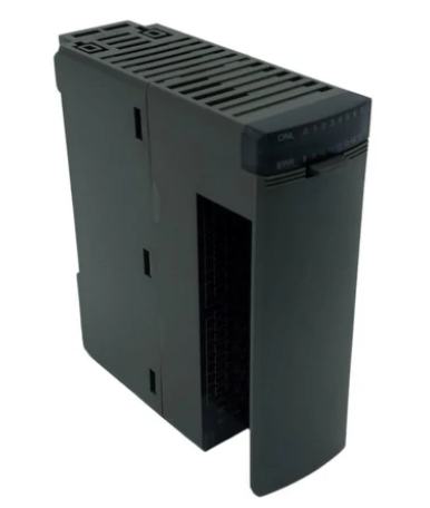
NP1Y16R-08 is positioned with "stable driving and precise output" as its core, and is the core module for expanding the number of digital output points in the NP1 series PLC. It adopts the NP1 series standardized module architecture, strictly follows the series interface specifications, and can be directly inserted into the compatible slots of the NP1 series rack without the need for additional adapter devices, achieving a plug and play expansion effect. Compared to the fixed output interface of integrated PLC, this module can flexibly increase or decrease output channels according to control requirements, effectively improving system configuration flexibility and reducing redundancy costs. At the same time, industrial grade reliability design ensures its continuous and stable operation in complex industrial environments, ensuring the accuracy of actuator actions.
FUJI NP1Y16R-08 Digital Output Module
Product core positioning and adaptation advantages
NP1Y16R-08 is positioned with "stable driving and precise output" as its core, and is the core module for expanding the number of digital output points in the NP1 series PLC. It adopts the NP1 series standardized module architecture, strictly follows the series interface specifications, and can be directly inserted into the compatible slots of the NP1 series rack without the need for additional adapter devices, achieving a plug and play expansion effect. Compared to the fixed output interface of integrated PLC, this module can flexibly increase or decrease output channels according to control requirements, effectively improving system configuration flexibility and reducing redundancy costs. At the same time, industrial grade reliability design ensures its continuous and stable operation in complex industrial environments, ensuring the accuracy of actuator actions.
Key technical characteristics
1. Multi channel grouping design, adapted to diverse control requirements
This module adopts a 16 channel digital output design, and a single module can achieve 16 independent digital signal outputs, which can effectively reduce rack slot occupation and optimize system integration space. The module adopts a grouping structure of 8 channels per group (the "08" in "16R-08" corresponds to the grouping specification), each group has an independent common terminal, supports differentiated access of loads of different voltage levels, and can simultaneously drive different types of loads such as DC 24V solenoid valves and AC 220V contactors without the need for additional relay modules, greatly improving the flexibility of load adaptation.
2. Relay output design, balancing reliability and safety
The module adopts industrial grade relays as output switching elements (where "R" represents relay output in the model), with mechanical contact isolation characteristics, which can achieve electrical isolation between the output circuit and the PLC system, effectively blocking the transmission of load side interference to the internal system. Relay contacts have high load tolerance, support AC/DC mixed load driving, and have a long contact action life (mechanical life can reach more than 10 million times), which can meet the high-frequency action requirements of industrial sites. At the same time, the relay output has natural arc extinguishing characteristics, which makes it more adaptable to inductive loads and does not require additional arc extinguishing devices.
3. Stable output response to ensure control synchronization
In response to the synchronous action requirements of actuators in industrial control, NP1Y16R-08 has optimized the output drive circuit. The relay action response time is controlled within 10ms, which can quickly respond to control instructions from the CPU module and ensure the synchronization of actions of multiple actuators. This stable output response characteristic makes it suitable for scenarios such as pipeline collaborative work and multi axis linkage control, avoiding process misalignment or equipment failure caused by output delay.
4. Multiple protection design to enhance system operation safety
The module is equipped with a comprehensive protection mechanism to ensure the safety of itself and load devices in all aspects. Firstly, each output has overcurrent protection function. When the load current exceeds the rated value, the output circuit can be quickly cut off to avoid relay contact erosion or damage to the load equipment; Secondly, the module has power supply reverse connection protection to prevent the internal circuit of the module from burning due to wiring errors; Thirdly, the group common end is equipped with fuse protection. When a short circuit fault occurs in a certain group load, the fault area can be isolated to avoid affecting the normal operation of other group channels.
5. Intuitive state monitoring, simplifying fault diagnosis
The front of the module is equipped with independent LED indicator lights for each channel, which can display the output status of the corresponding channel in real time ("on" indicates output conduction, "off" indicates output disconnection). Engineers can quickly judge the working status of each channel by visual inspection. At the same time, the module communicates in real-time with the CPU through the bus, and can provide feedback on output circuit faults (such as overload, short circuit), power supply abnormalities, and other information to the CPU. With the help of Fuji's dedicated programming software, the fault point can be accurately located, greatly reducing the troubleshooting time and improving system maintenance efficiency.
6. Convenient wiring and installation to improve project efficiency
The module adopts a spring type terminal design, and the wiring operation does not require special tools. The wire insertion and removal is convenient and firmly fixed, which can effectively resist the problem of loose wiring caused by industrial site vibration. The terminal block is clearly labeled with channel numbers, grouped common terminals, and power interfaces, and matched with the grouping identification on the module surface, making it easy for engineers to quickly identify wiring and reduce human errors during installation and maintenance. The module adopts a standard DIN rail installation method, which has good compatibility with the NP1 series rack and is flexible and efficient in installation and disassembly.
Main technical parameters
Module Type
Digital output module (relay output)
Focusing on the driving and control of industrial field actuators
Number of output channels
16 channels, divided into 2 groups (8 channels per group)
Each group has an independent public end that supports differentiated load access
output method
Relay contact output (normally open)
Mechanical contact isolation, suitable for AC/DC loads
Output response time
≤ 10ms (suction/release)
Quickly respond to control instructions to ensure action synchronization
Rated load voltage
AC 250V / DC 30V
Wide voltage range, suitable for various industrial loads
Single channel rated load current
2A(AC/DC)
Can directly drive low to medium power actuators
Group rated current
10A per group (total current not exceeding 16A)
Meet the current demand for multi-channel simultaneous operation
isolation method
Optoelectronic isolation (between channels/systems)
Isolation voltage 2500V AC/1min, strong anti-interference ability
wiring method
Spring terminal
Suitable for wire specifications of 0.2-2.5mm ², with secure and convenient wiring
Working temperature range
-10℃-60℃
Wide temperature design, suitable for high and low temperature industrial scenarios
Storage temperature range
-20℃-70℃
Meet storage requirements in harsh environments
Humidity adaptation range
10% -90% RH (no condensation)
Adapt to high humidity industrial environments and avoid condensation damage
Dimensions (W × H × D)
Approximately 45 × 100 × 120mm (reference value)
Compact design, saving rack installation space
Typical application scenarios
1. Automated production line execution control: In scenarios such as automotive assembly lines and electronic component assembly lines, modules can drive equipment such as solenoid valves (controlling cylinder action), conveyor motor contactors, indicator lights (status prompts), etc. at each workstation to achieve process flow, workpiece positioning, equipment start stop and other actions based on CPU instructions, ensuring efficient and coordinated operation of the production line.
2. Mechanical manufacturing equipment drive: In CNC machine tools, injection molding machines, printing machines and other equipment, it is used to control the spindle start stop contactor, feed system solenoid valve, cooling pump motor, alarm indicator light and other actuators, and cooperate with input module signals to achieve automatic processing flow control and abnormal warning of the equipment.
3. Energy and power equipment control: In distribution systems, photovoltaic inverters, and wind turbine control systems, devices such as circuit breaker opening and closing coils, isolation switch actuators, and status indicator lights are driven to achieve remote control and visualization of power equipment operation status, improving the automation level of energy management.
4. Logistics warehousing execution system: In the three-dimensional warehouse and intelligent sorting line, control the stacker crane lifting/translation motor contactor, conveyor belt drive solenoid valve, cargo position indicator light and other equipment to achieve precise storage, sorting and transportation of goods according to the instructions of the warehouse management system, and improve the automation efficiency of logistics warehousing.
Installation and usage precautions
-The module installation needs to match the NP1 series compatible rack. When inserting into the slot, ensure that the module's gold fingers are fully in contact with the rack bus interface and locked with fixing screws to prevent poor contact or module detachment caused by vibration.
-Before wiring, the main power supply of the PLC system and the module load power supply must be cut off. The output circuit wiring must strictly distinguish between grouped common terminals to avoid mixing loads of different voltage levels; Each output wire should correspond to the channel number of the terminal block to prevent load misoperation caused by misconnection.
-The installation environment of the module should be kept away from strong magnetic fields (such as large transformers and electromagnets), strong heat sources (such as heating furnaces and high-power resistors), and corrosive gases, avoiding direct sunlight and rainwater erosion, and ensuring that the environmental temperature and humidity meet the product specifications.
-When driving inductive loads such as motors and solenoid valves, although relays have a certain arc extinguishing ability, it is recommended to parallel freewheeling diodes (DC loads) or RC absorption circuits (AC loads) at both ends of the load to extend the contact life of the relay and reduce interference.
-Before using the module for the first time, it is necessary to configure the module address through programming software (if necessary) and conduct output function testing to verify the accuracy of each channel's output action one by one. After confirming that there are no abnormalities, connect the actual load and put it into operation.
-During regular maintenance, it is necessary to check whether the wiring terminals are loose, whether the LED indicator lights are normal, and clean the dust on the surface of the module and inside the rack; If faults such as relay contact adhesion or abnormal output are found, the power should be cut off and the module should be replaced in a timely manner to avoid damage to the load equipment.
- User name Member Level Quantity Specification Purchase Date
- Satisfaction :
-


