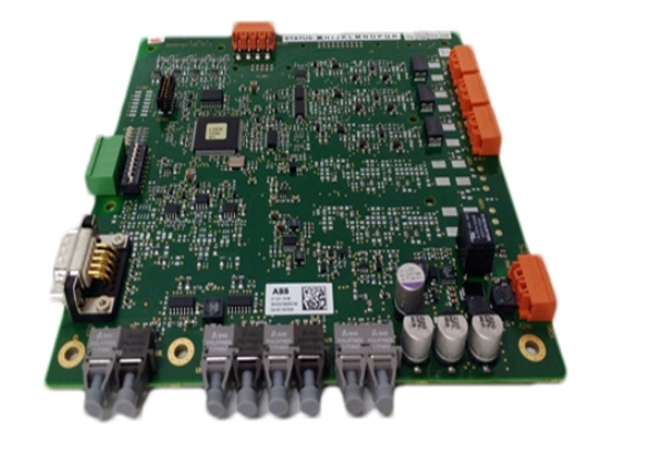
The ABB SCYC51020 58052582G pulse trigger board is a core control component developed by ABB for industrial power electronics transformation scenarios. It is designed to provide precise trigger signals for power semiconductor devices such as thyristors (SCR) and insulated gate bipolar transistors (IGBT), and is a key "bridge" connecting control units and power execution units. This product integrates functions such as signal isolation, pulse generation, and fault feedback. It can convert weak electrical commands output by PLC or dedicated controllers into strong electrical pulse signals that meet the requirements of power device conduction/shutdown. It is widely used in power electronic systems such as frequency converters, rectification devices, intermediate frequency power supplies, and reactive power compensation equipment to ensure the efficiency and stability of the energy conversion process.
ABB SCYC51020 58052582G programmable Logic Controller
Product Overview
The ABB SCYC51020 58052582G pulse trigger board is a core control component developed by ABB for industrial power electronics transformation scenarios. It is designed to provide precise trigger signals for power semiconductor devices such as thyristors (SCR) and insulated gate bipolar transistors (IGBT), and is a key "bridge" connecting control units and power execution units. This product integrates functions such as signal isolation, pulse generation, and fault feedback. It can convert weak electrical commands output by PLC or dedicated controllers into strong electrical pulse signals that meet the requirements of power device conduction/shutdown. It is widely used in power electronic systems such as frequency converters, rectification devices, intermediate frequency power supplies, and reactive power compensation equipment to ensure the efficiency and stability of the energy conversion process.
Based on ABB's technological accumulation in the field of power control, this trigger board adopts industrial grade components and anti-interference design, which can work stably in complex industrial environments with high temperature and high electromagnetic interference. Its triggering accuracy and response speed are at the leading level in the industry, effectively improving the operational reliability of power electronic devices and reducing the risk of device damage.
Core functions and technical features
2.1 Core Functions
-High precision pulse generation: supports phase separated pulse output, trigger angle adjustment range of 0 ° -180 °, pulse width continuously adjustable from 10 μ s to 100 μ s, trigger timing accuracy of ± 0.1 μ s, can adapt to different types of thyristors and IGBTs, and meet the needs of various power conversion topologies such as rectification, inversion, and chopping.
-Strong and weak electrical isolation protection: Equipped with a built-in photoelectric isolation module, the insulation resistance between the control circuit and the power pulse circuit is ≥ 2500Vrms, effectively blocking the interference of high voltage and high current in the power circuit on the control unit, while protecting the safety of operators and backend equipment.
-Multi type signal adaptation: compatible with both analog (4-20mA, 0-5V) and digital (TTL level) input methods, it can seamlessly integrate with ABB AC500 series PLC, DCS systems, and third-party controllers without the need for additional signal conversion modules, simplifying system integration.
-Fault monitoring and interlocking: It has the function of collecting fault signals such as overcurrent, overvoltage, and device overheating. When abnormalities are detected, the trigger pulse is quickly cut off within 1ms and a fault alarm signal is output to achieve active protection of power devices and avoid the expansion of faults.
-Synchronous signal tracking: Equipped with a built-in synchronous transformer interface, it can track the grid voltage synchronous signal in real time, ensuring precise matching between pulse output and grid frequency, preventing triggering disorder caused by grid fluctuations, and improving system operation stability.
2.2 Technical Features
-High reliability structure: adopting modular design, the core circuit has undergone three anti treatments (anti moisture, anti salt spray, anti mold), passed the IEC 60068 environmental adaptability test, the working temperature range is -20 ℃~+65 ℃, and the average time between failures (MTBF) exceeds 80000 hours.
-Strong anti-interference performance: With EMC level three anti-interference ability, it can resist electromagnetic radiation and conducted interference in industrial sites, and can still stably output pulse signals in scenarios where strong interference equipment such as frequency converters and welding machines coexist.
-Convenient debugging features: onboard LED status indicator light, which can intuitively display power supply, input signal, pulse output, and fault status; Reserved testing interface, pulse parameters can be modified online through dedicated debugging software without disassembling the equipment.
-Wide power supply adaptation: Supports DC 24V ± 15% wide voltage input, built-in power supply stabilization circuit, can adapt to power fluctuations in industrial sites, and reduce equipment failures caused by unstable power supply.
Key technical parameters
parameter category
Specific parameters
Instructions
Model identification
SCYC51020 58052582G
SCYC51020 is the product series number, 58052582G is the production batch/configuration code
Applicable device types
Thyristor (SCR), IGBT, GTO
Support triggering of power devices with rated current ≤ 3000A
input signal
Analog quantity: 4-20mA/0-5V; Digital quantity: TTL 5V
Select input signal type through dip switch
Pulse output parameters
Amplitude: 15V-24V; Current: ≥ 1A; Rising edge time: ≤ 1 μ s
Meet the fast conduction requirements of power devices
synchronization method
Grid synchronization (50Hz/60Hz), internal synchronization
Synchronization error ≤ 0.5 °
working power supply
DC 24V±15%; Power consumption: ≤ 8W
Equipped with reverse power protection function
isolation level
Control circuit and output circuit: 2500Vrms/1min
Compliant with IEC 61010-1 safety standard
Installation method
DIN rail installation (35mm) or screw fixation
Size: 100mm x 80mm x 40mm (length x width x height)
Protection level
IP20
Suitable for installation inside control cabinets
Applicable scenarios and typical applications
This pulse trigger board is widely used in various power electronic conversion systems due to its high adaptability and stability. Typical scenarios include:
1. Industrial frequency converter: In the power unit of the high-voltage frequency converter, precise triggering pulses are provided to the IGBT module to achieve the conversion of input AC power to output adjustable frequency AC power, which is used for speed control of loads such as fans and pumps, reducing energy consumption.
2. Rectification device: In high-power rectification equipment in industries such as electrochemistry and electroplating, the thyristor conduction angle is controlled to convert alternating current into direct current, achieving continuous regulation of output voltage/current and ensuring stable production processes.
3. Medium frequency induction heating equipment: In the medium frequency power supply of metal heat treatment, forging and other fields, IGBT is triggered to form a high-frequency oscillation circuit, converting electrical energy into thermal energy to achieve rapid heating of metal materials and improve heating efficiency.
4. Reactive power compensation device: In the reactive power compensation system (SVC) of the power grid, the thyristor is controlled to switch capacitors or reactors, compensating for the reactive power of the power grid in real time, improving the power factor, and stabilizing the power grid voltage.
5. Rail Transit Traction System: In the traction converters of subways and light rails, power devices are triggered to convert DC and AC electricity, providing stable power to the traction motors and ensuring smooth train operation.
Installation and usage precautions
5.1 Installation specifications
-Before installation, it is necessary to verify that the product model matches the parameters of the power device, check that the circuit board is not deformed, the pins are not oxidized, and that the accessories (fixing parts, wiring terminals) are complete.
-The installation location should be far away from high-power heating devices (such as resistors and transformers), ensuring a distance of ≥ 5cm from surrounding devices to ensure good ventilation and heat dissipation.
-When wiring, it is necessary to strictly distinguish between the control circuit and the power circuit. The control line should be shielded and grounded at one end to avoid parallel wiring with the power cable and reduce electromagnetic interference.
-The pulse output line should use high-temperature resistant silicone wire with a length of ≤ 2m to avoid excessive bending. The wiring terminals should be tightened to prevent poor contact from causing pulse attenuation.
5.2 Key points of use and maintenance
-Before the first power on, it is necessary to use a multimeter to check the voltage and polarity of the power supply. After confirming that there are no errors, the power supply can be connected to avoid overvoltage or reverse connection that may damage the power module.
-According to the power device model, parameters such as pulse width and trigger delay can be set through onboard dip switches or debugging software. After parameter modification, the device needs to be restarted to take effect.
-During operation, it is necessary to regularly check the status of the LED indicator lights: the power light (green) is always on, the pulse light (yellow) flashes with the triggering frequency to indicate a normal state, and the red light is on to indicate a fault.
-Regularly clean the dust on the surface of the circuit board, turn off the power and use a dry brush during cleaning, avoid using wet cloths or cleaning agents, and prevent short circuits.
-Fault repair must be carried out by professional personnel. It is prohibited to dismantle isolation modules or modify circuits without authorization. After repair, insulation testing must be conducted before they can be put back into use.
- User name Member Level Quantity Specification Purchase Date
- Satisfaction :
-


