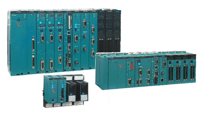
ABB SPDSO14 Digital Output Slave
Overview
Product Definition and Function: ABB SPDSO14 Digital Output Slave is an important component in industrial automation control systems. It is mainly used to convert digital signals from control systems (e.g. PLC, DCS, etc.) into actual physical outputs to drive external devices (e.g. relays, indicators, solenoid valves, etc.). This kind of module is able to realise the switching control of various devices in the industrial site and ensure that the industrial process is carried out according to the predetermined logic and sequence.
Working Principle
Signal reception and processing:
Input interfaces and signal types: The SPDSO14 module has several digital input channels for receiving digital signals from the main controller or host system. These digital signals are typically binary logic level signals such as TTL (Transistor-Transistor Logic) levels or CMOS (Complementary Metal-Oxide-Semiconductor) levels; TTL levels typically range from 2V to 5V high and 0V to 0.8V low; CMOS levels range depending on the specific device. These signals enter the internal circuitry through the module's input pins.
Signal Buffering and Conversion: When a signal enters the module, it first passes through a signal buffer circuit. The purpose of the signal buffer circuit is to enhance the driving capability of the input signal and prevent the signal from being degraded by interference during transmission. At the same time, the module performs level conversion (if required) on the signal to convert the input signal to a standard level that can be handled by the internal circuitry. For example, if the input signal is an external signal that does not meet the module's internal operating level requirements, it is converted to an appropriate level by a level conversion circuit to ensure that the signal can be correctly identified and processed.
Output driving mechanism:
Output Interface and Load Capability: The processed digital signals are directed to the output interface for driving external devices. the output interface of the SPDSO14 module is usually a port that can provide enough drive current and voltage to drive various loads. For relay drives, the module can output enough current to cause the relay coil to engage, thus enabling on-off control of the circuit. The amount of output current depends on the design of the module, and can typically be several hundred milliamps (e.g., 0.5A - 1A) to meet the driving requirements of most relays. For indicator light drive, the module can provide suitable voltage and current to make the indicator light on or off, indicating the status of the device. For solenoid valve drive, the output signal can control the opening or closing of the solenoid valve, thus controlling the flow of fluid (e.g. gas, liquid).
Performance features
High reliability: industrial-grade design and manufacturing process, with high reliability and stability, able to operate for a long time in harsh industrial environments. Its shell generally has a certain level of protection (such as IP30 or higher), can be dustproof, water splash. The internal circuits are strictly designed for electromagnetic compatibility (EMC), which can resist the electromagnetic interference (EMI) and radio frequency interference (RFI) in the industrial field and ensure the accurate output of digital signals and normal control of external devices.
Multi-Channel Output Function: With multiple digital output channels, it can control multiple external devices at the same time. The number of channels varies depending on the specific model, typically 8 - 16 output channels. This multi-channel design improves the integration and application range of the module, for example, in an automated production line control system, it can simultaneously control the start/stop of multiple motors, the on/off of multiple indicator lights, and the opening/closing of multiple valves, etc., so as to realise the centralised control of the entire production line.
Flexible Configuration and Programming Capability: The attributes of the channel, such as output mode (normally open or normally closed), initial state, etc., can be configured through software or hardware settings (e.g., dip switches). At the same time, the module can work with different control systems and be programmed to realise a variety of complex control logics. For example, in an intelligent building automation system, the on/off state of equipment such as lighting systems, HVAC (heating, ventilation and air conditioning) systems, etc. can be programmed to be controlled according to different conditions such as time and temperature.
Rapid Response Capability: The ability to respond quickly to input signals and the short conversion time of output signals. Generally speaking, from the input signal change to the output signal corresponding change in microseconds to milliseconds, for example, the typical output signal conversion time can reach 1 - 10 microseconds, this fast response ability to meet the requirements of the industrial process of rapid control of the equipment, such as in some high-speed automation equipment, rapid control of the motor start and stop or valve opening and closing.
Technical Parameters
Input parameters:
Number of digital input channels and level standards: typically 8 - 16 digital input channels, supporting TTL levels (high level 2V - 5V, low level 0V - 0.8V) or CMOS levels (depending on the specific device).
Input signal frequency range (if applicable): for some applications where pulsed signals need to be processed, the input signal frequency range can be from a few Hertz to tens of kilohertz, e.g. 0 - 10kHz, depending on the design of the module and the application scenario.
Output parameters:
Number of digital output channels and driving capacity: generally there are 8 - 16 digital output channels, each channel can provide a certain driving current, such as 0.5A - 1A continuous output current to drive relays, indicators, solenoid valves and other loads. The output voltage range depends on the module design and external equipment requirements, generally can be between a few volts to tens of volts, such as 5V - 30V.
Output Signal Type and Logic Level: The output signal is a digital switching signal, and the logic level is usually high (e.g., 5V or 12V) for ‘on’ state, and low (e.g., 0V) for ‘off’ state.
Performance Parameters:
Response Time: The response time of the output signal to the input signal is usually between 1 - 10 microseconds, which can quickly achieve the conversion and output of the signal.
Isolation Characteristics (if any): Optocoupler isolation is used between the input and output circuits, and the isolation voltage can be up to several thousand volts (e.g. 2500V - 5000V), which effectively prevents external disturbances from electrically affecting the internal circuits.
Physical parameters:
Dimensions: The external dimensions are generally designed according to the installation requirements and may range from 10cm - 20cm in length, 5cm - 10cm in width and 3cm - 8cm in thickness, allowing for easy mounting in control cabinets or specific locations in the equipment, e.g. via standard DIN rail mounting.
Weight: Light weight, typically between 100g - 500g, not overly burdensome to the installation and structure of the equipment.
Environmental parameters:
Operating temperature range: Can be operated in a temperature range of - 20°C - + 60°C, adapted to different industrial site temperature conditions.
Humidity range: Relative humidity range is usually 10% - 90% (non-condensing), ensuring normal operation in different humidity environments.

- User name Member Level Quantity Specification Purchase Date
- Satisfaction :
-


