
GP477R Engineering Installation
3.2 Wiring steps for power terminals
Power off confirmation: Before connecting any wires, make sure that the power cord is completely disconnected from the power supply network and the circuit breaker is in the OFF position.
Open the terminal cover: Use a Phillips screwdriver to unscrew the protective cover on the power input terminal block.
Terminal definition: The terminal block has three markings:
L: AC100V live line
N: AC100V neutral wire
FG: Grounding terminal (connected to GP casing)
Use circular terminals with insulated sleeves: To prevent short circuits caused by loose screws, it is recommended to use JST V2-MS3 or equivalent circular cold pressed terminals with insulated sleeves. The maximum cross-sectional area of the wire is 2mm ² (approximately 14AWG).
Wiring: Loosen the corresponding screw, insert the wire with the pressed terminal and tighten it again, with a torque of 0.5-0.6 N · m.
Grounding: The FG terminal must be directly connected to the grounding copper bar of the control cabinet using a separate wire, and the grounding resistance should be less than 100 Ω. It is prohibited to short-circuit FG and N lines, nor to suspend them, otherwise the anti-interference ability of GP will sharply decrease.
3.3 Anti interference measures for power supply
It is recommended to parallel a surge absorber (varistor) at the power input end to suppress spikes caused by lightning strikes or inductive load switching.
If the factory power grid has severe noise (such as a large number of frequency converters), an isolation transformer or noise filtering transformer should be installed at the front end of the GP power supply.
The power cord should be as short as possible and routed separately from the power and motor lines to avoid bundling in the same cable tray.
Twisting the power cord into a twisted pair before connecting it to the terminal can further improve the common mode noise suppression capability.
Serial interface (RS-232C/RS-422)
The GP477R is equipped with a 25 pin D-sub female socket (located on the back of the body) that can be configured in RS-232C or RS-422 mode for connecting PLCs, computers, or other master station equipment. This interface supports full duplex communication, with a maximum baud rate typically reaching 115.2kbps (depending on the system program version).
4.1 Pin Allocation Table
Pin signal name description Pin signal name description
1 FG frame grounding 14 VCC+5V ± 5% output 0.25A
2 SD sends data (RS-232C) 15 SDB sends data B (RS-422)
3 RD receives data (RS-232C) 16 RDB receives data B (RS-422)
4 RS request sent (RS-232C) 17 NC not connected
5 CS clear send (RS-232C) 18 CSB clear send B (RS-422)
6 NC-19 ERB allows reception of B (RS-422)
7 SG signal grounded 20 ER allows reception (RS-232C)
8 CD Carrier Detection (RS-232C) 21 CSA Clear Transmission A (RS-422)
9 TRMX terminal resistor (RS-422) 22 ERA allows receiving A (RS-422)
10 RDA Received Data A (RS-422) 23 Reserved
11 SDA sends data A (RS-422) 24 NC not connected
12 NC-25 Reserved
13 NC -
Important precautions:
Pin 14 (VCC) can output a+5V/0.25A power supply to external converters or low-power devices. This output has no overload protection, and it must be ensured that the total current does not exceed the rated value during use, otherwise it will damage the internal power circuit of the GP.
In RS-422 mode, pin 9 (TRMX) is required to connect the terminal resistor. When GP is located at the end of the bus, TRMX should be short circuited to RDA (pin 10); The specific short-circuit method depends on the communication protocol, and it is generally recommended to connect only the two end devices to a 120 Ω resistor when connecting multiple points.
The signal ground (pin 7 SG) must be connected to the signal ground of the opposite device, otherwise it may cause common mode voltage damage to the interface chip.
4.2 Recommended connectors and cables
Connector: OMRON XM2A-501 (25 pin male) with threaded locking.
Shell: OMRON XM2S-2511, with matching screws of M2.6 × 0.45 coarse teeth.
Cable: Hitachi cable CO-MA-VV-SB5P × 28AWG or other twisted pair shielded cable (at least 5 pairs of wires) is recommended. RS-232C can use standard direct serial cable, while RS-422 requires twisted pair transmission of differential signals.
4.3 Typical Wiring Examples
RS-232C three wire system (communicating with PC serial port): GP's SD (2) → PC's RD, GP's RD (3) → PC's SD, GP's SG (7) → PC's SG. If hardware handshake is required, GP's RS (4) and CS (5) can be connected to the corresponding signal of the PC, but most applications only require three wires.
RS-422 four wire system (communicating with PLC): SDA of GP (11) → RDA of PLC, SDB of GP (15) → RDB of PLC, RDA of GP (10) → SDA of PLC, RDB of GP (16) → SDB of PLC, while connecting SG (7) of GP to SG of PLC.
Printer interface
The GP477R also has a 14 pin flat interface on the back (Centronics compatible) for connecting to parallel printers to print alarm records or hard copy screens. The interface adopts Fujitsu FCN-787P014-G/R connector.
Pin Function Summary (Based on Original Document Inference):
Standard parallel port signals such as data cable STB, D0-D7, BUSY, etc.
- ABB
- General Electric
- EMERSON
- Honeywell
- HIMA
- ALSTOM
- Rolls-Royce
- MOTOROLA
- Rockwell
- Siemens
- Woodward
- YOKOGAWA
- FOXBORO
- KOLLMORGEN
- MOOG
- KB
- YAMAHA
- BENDER
- TEKTRONIX
- Westinghouse
- AMAT
- AB
- XYCOM
- Yaskawa
- B&R
- Schneider
- Kongsberg
- NI
- WATLOW
- ProSoft
- SEW
- ADVANCED
- Reliance
- TRICONEX
- METSO
- MAN
- Advantest
- STUDER
- KONGSBERG
- DANAHER MOTION
- Bently
- Galil
- EATON
- MOLEX
- DEIF
- B&W
- ZYGO
- Aerotech
- DANFOSS
- Beijer
- Moxa
- Rexroth
- Johnson
- WAGO
- TOSHIBA
- BMCM
- SMC
- HITACHI
- HIRSCHMANN
- Application field
- XP POWER
- CTI
- TRICON
- STOBER
- Thinklogical
- Horner Automation
- Meggitt
- Fanuc
- Baldor
- SHINKAWA
- Other Brands
- UniOP
- KUKA
- Iba
-
 Omron C500-TU001 3G2A5-TU001 PLC Teaching Box
 -
 Saia PCD4.M110 PLC CPU Module Programmable Logic Controller
 -
 Yaskawa SGMPH-04AAA61D-OY Sigma-II AC Servo Motor 400W
 -
 Sumitomo Cyclo FAS35-119 Precision Cycloidal Gear Reducer
 -
 Omron IDSC-C1DR-A-E ID Controller PLC Unit
 -
 Omron F350-L100E OVL Image Processing Unit Vision System PLC
 -
 Omron CJ1W-F159 Load Cell Interface Weighing Module
 -
 Bticino MA250 T7314A250 Megatiker PLC Module
 -
 Mitsubishi AJ71QLP21G GI Fiber Optic Network Module
 -
 Omron R88D-HS10 Servo Drive DC Type
 -
 Omron FZ3-L355 Vision Sensor Controller
 -
 Omron C200H-CPU23-E CPU Unit PLC
 -
 Moeller UNIOP MI4-110-KG2 Text Display HMI
 -
 KEB COMBIVERT F5 07.F5.B1B-3B0A Inverter
 -
 Toshiba VFS15-4037PL-W Variable Frequency Drive
 -
 Omron CS1W-SCU31-V1 Serial Communication Unit
 -
 LSIS SV055iG5A-4 AC Drive 5.5kW
 -
Omron CJ1W-F159 Loadcell Interface Unit
-
 Omron CQM1-TC001 Temperature Control Module
 -
 Mitsubishi FX5-SF-MU4T5 Safety Module
 -
 Omron C1000H-CPU01-EV1 CPU Unit
 -
 Yaskawa SGDV-2R8A11A Servo Drive 400V
 -
 Omron 3G3HV-A4055-CUE VFD 5.5kW
 -
 Omron F160-C15E Vision Sensor Controller
 -
 Schneider ELAU PMC-2 Servo Drive 2.2kW
 -
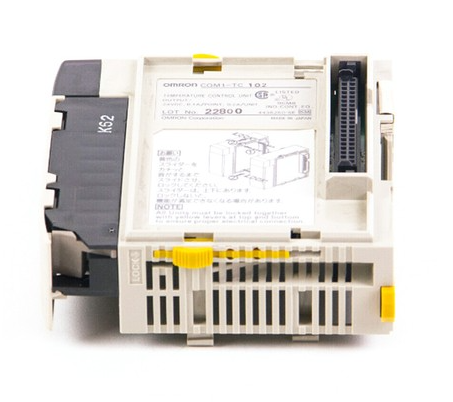 Omron CQM1-TC102 Temperature Control Unit
 -
 Omron CS1G-CPU65-EV1 CPU Unit CS1 Series
 -
 Omron CJ1H-CPU66H CPU Unit High Performance
 -
 Saia PCD4.H320 Analog Input Module
 -
 Omron NX-EIC202 EtherNet/IP Coupler Unit
 -
 Omron R88M-H75030 Servo Motor OMNUC Series 750W
 -
 Omron F500-VS Vision Sensor F500 Series Machine Vision
 -
 Omron R88S-H306G Power Unit for Servo Motor OMNUC Series
 -
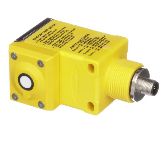 Banner Q45ULIU64ACR Ultrasonic Sensor Q45U Series Proximity Mode
 -
 Allen Bradley 1756-IRT8I RTD Thermocouple Input Module ControlLogix
 -
 Siemens Sinumerik 840D SL NCU 720.3B with PLC 317-3 PN DP
 -
 Kollmorgen SERVOSTAR J-06 Servo Drive Danaher Motion
 -
 Omron NX-ECC202 EtherCAT Coupler Unit NX Series
 -
 OMRON CS1W-SCU31-V1 Serial Unit
 -
 Beckhoff CX5020-0110 Embedded PC PLC
 -
 Omron CJ1M-CPU13-ETN CPU Unit Ethernet
 -
 Omron C60H-C1DR-DE-V1 PLC Controller
 -
Omron CJ1W-PTS51 Thermocouple Input Unit
-
 Omron CJ1W-DA021 Analog Output Module 2 Ch
 -
 Omron CS1W-MAD44 Analog I/O Module
 -
 Omron C500-PRW05-V1 PROM Writer
 -
 Omron CJ1G-CPU45H Loop Control CPU Unit
 -
 ABB PSTX570-600-70 Soft Starter 570A
 -
 PTF Electronic SCR W1Z Power Controller 1150mm
 -
 Omron C500-CT012 High Speed Counter Unit
 -
 NBC Electronics MOD.ES 3 Ton Load Cell
 -
 DeltaOmega XML2 0060 45 4 S A Servo
 -
 REM EC235 Counter Module
 -
 Motor Power SKA DDR 148.30.8.19 Torque Motor
 -
 Delta Tau 4-Axis Interface PLC
 -
 Yokogawa PC10020 AA00 L1Z002 Position Controller
 -
 OMRON C60H-C5DR-DE-V1 PLC
 -
 Burgess PCD4.H320 Motion Control PLC
 -
 Parker SMB14245155242ID644 Servo Motor
 -
 Baumuller PLC-01 BMC-M-PLC-01-11-02 PLC
 -
 Omron CPM2B-32C2D1T-D12 PLC Compact Controller
 -
 Ansaldo SVTS076FBNF Industrial Drive 76KVA
 -
 Omron C500-PRW06 PROM Writer Programmer
 -
 Mitsubishi FX0N-24MR-ES PLC Compact Controller
 -
 Omron R88D-HS22 Servo Drive OMNUC H Series
 -
 Omron CJ1M-CPU11-ETN CPU Unit PLC
 -
 Bosch Rexroth 109129B051 HCP08 PLC Board
 -
 Landis Gyr PCD4.M125 PLC CPU Module
 -
 Nidec SP4202 Variable Frequency Drive 22kW
 -
 Puls QS40.241 Power Supply 40A 24VDC
 -
 Eaton XV-102-B6-35MQR-10-PLC Touch Panel
 -
 Omron ZFX-C15 Vision Sensor Controller
 -
 Kyosan PHS-4C-AN1 Servo Control Power Supply
 -
 Omron NX-ECC201 EtherCAT Coupler Unit
 -
 Omron C20-CPU83E CPU Unit 3G2C7-CPU83E
 -
 Omron FZ-SQ100F Vision Sensor Camera
 -
 Siemens 6SL3352-6BE00-0AA1 Power Supply Board
 -
 ABB AO815 3BSE052605R1 Analog Output Module
 -
 Siemens C98043-A1200-L Control Card
 -
 Allen-Bradley 1336-BDB-SP72D Gate Drive PCB
 -
 ST2000 34 Algorab Graphic PLC Terminal
 -
 OMRON C200HW-PRM21 Profibus DP Module
 -
 Siemens 2020964-001 DPM Base Board
 -
 OMRON CJ1W-V600C11 ID Controller Unit
 -
 Telemecanique TSX7 Series PLC Module
 -
 Okuma 1911-2861-0236049 Graphic Card Module
 -
 Parker HPD2S2N Servo Driver
 -
 OMRON FQ2-D31 Touch Finder Vision Sensor
 -
 OMRON C500-LK007 Host Link Unit
 -
 OMRON CJ1W-SCU32 Serial Communication Unit
 -
 Edwards C41901000 24V Solenoid Valve
 -
 ABB Procontic CS31 07 KR 91 PLC Controller
 -
 Siemens 7KG7750-0AA01-0AA0 Power Meter
 -
 Demag NC4K Compact PLC Controller
 -
 ABB SAPC 35 PAC/PP8482 Pulse Amplifier Board
 -
 Yaskawa SGMGH-09DCA6H-OY Servo Motor 850W
 -
 Saia PCD4.M445 Processor Module PLC
 -
 Yaskawa SGDH-04AE Servo Drive 400W 200V
 -
 Omron H8PR-24 Cam Positioner
 -
 Omron F150-C10E-2 Vision Sensor
 -
 OMRON 3G3MX2-A4015-E Inverter
 -
 Pro face GP577R-TC11 HMI
 -
 Pro face GP477R-EG11 HMI
 -
 ABB Pluto S20 V2 CFS Safety PLC
 -
 Siemens A5E00825002 IGD Board
 -
 Sakae SH40JHK-ZU-3S1R3G-10621B Joystick
 -
 Siemens 3RK1105-1AE04-0CA0 Safety Relay
 -
 Allen Bradley 1775-MEF Memory Module
 -
 OMRON CS1H-CPU63-H PLC CPU Unit
 -
 OMRON F150-C15E-3 Vision Sensor
 -
 Omron CJ1W-DA041 Analog Output Module
 -
 Saia PCD4.M440 PLC Module PCD4.M44
 -
 Steiel S595 PH Industrial Controller
 -
 VT650 PC Windows 2000 HMI Panel PC
 -
 Omron C200H-AD003 Analog Input Module
 -
 Omron CJ1W-V600C11 ID Sensor Unit
 -
 Coherent 250W Laser Adjustable Lens Head
 -
 Omron CQM1-AD042 Analog Input Module
 -
 SICK XKS09-HTBM-S02 Wire Draw Absolute Encoder
 -
 Omron 3F88L-P3A-E Cam Positioner PLC
 -
 OMRON R88M-H1K130 Servo Motor
 -
 SIEMENS 6ES7 331-7KB01-0AB0 SM331 Analog Input Module
 -
 LANDIS PCD4.M110 Processor Module
 -
 OMRON NT631C-ST151-EV2 HMI Touch Screen
 -
 TE.CO Grey Cable TFX 4G 1.5 ST 564mt UNEL Grey
 -
 OMRON R88D-H310G Servo Drive
 -
 ABB SACE SM3 630 630A PLC Switch
 -
 OMRON DRT2-AD04H Analog Input Terminal


