
GP477R Engineering Installation
GP477R Touch Screen Installation and Interface Configuration Guide
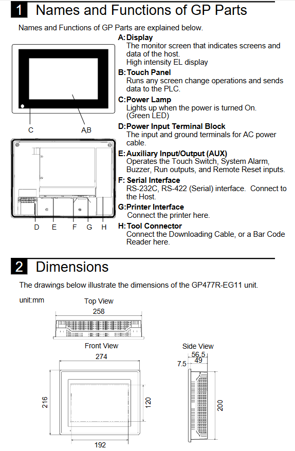
In the process of renovating old production lines or repairing equipment, engineers often need to face human-machine interface (HMI) models from ten years ago or even earlier. The Pro face GP477R series (such as GP477R-EG11) is one of the classic 10 inch touch screens, widely used in industries such as packaging, printing, and machine tools. This model adopts AC100V power supply, provides RS-232C/422 dual standard serial communication, and is equipped with independent printer interface and AUX auxiliary input/output, which can reliably interact with various PLCs and external devices. However, due to the age, it is difficult to obtain the original factory paper manual. Improper handling of wiring and installation details can result in communication abnormalities, touch failures, and even equipment damage or electric shock accidents. Based on the original technical data of this model, this article systematically reviews the entire process of GP477R from unboxing inspection, hole fixing, power grounding to pin definition and anti-interference measures of various communication ports, aiming to provide a highly operational reference document for on-site engineers.
Open box inspection and confirmation of selected accessories
1.1 Standard Packaging Content
After unpacking, the first thing to check is whether the following items are complete:
One GP477R host
Install 4 fasteners (installation clips)
Sealing gasket (pre installed in the grooves around the body)
Quick User Guide (Single Page)
If any missing or damaged items are found during transportation, the local agent should be contacted immediately. It should be noted that this model of host does not include any communication cables, programming software, and installation tools, which need to be purchased separately.
1.2 Common optional accessories
User Manual: GP477R/577R Series User Manual, providing detailed instructions on screen editing and system settings.
Programming cable: A serial download cable (usually an RS-232C crossover cable) used to connect a PC to a GP.
Screen editing software: Pro face GP-PRO/PBIII or earlier GP Editor, depending on the operating system version.
Adapter: If a non-standard interface PLC needs to be connected, a dedicated conversion adapter may be required.
The most common difficulty encountered by on-site engineers when replacing old equipment is the loss or damage of the original cables. Therefore, it is recommended to make a self-made communication line according to the pin definition in Section 3 in advance.
Mechanical installation and waterproofing measures
2.1 Inspection of sealing gaskets
The GP477R is designed with a frontal protection level of IP65 (when correctly installed on the control cabinet panel), and its key component is the rubber sealing gasket installed in the groove around the display screen. Before installation, the host display screen must be placed facing down on a flat surface, and the gasket must be carefully checked for complete insertion into the slot, no distortion or damage. If the gasket falls off or ages and cracks, the subsequent waterproof effect will be completely lost, and the gasket of the same specification must be replaced.
2.2 Panel Hole Size
According to the external dimension diagram in the manual (page 3 of this document), the installation opening of GP477R-EG11 is rectangular, and the specific dimensions need to be obtained from the original mechanical drawing. It is generally recommended to cut the control cabinet panel according to the following general rules:
The edge of the opening must be flat and free of burrs. It is recommended to use laser or wire cutting for processing.
The opening size should be slightly larger than the GP rear shell, but it must be ensured that the sealing ring can be fully compressed. The recommended standard opening tolerance is+0.5/-0mm.
The thickness of the panel material should be between 1.5mm and 5mm to ensure effective clamping of the fasteners.
2.3 Fixed method
Insert GP477R into the opening from the front (outer side) of the panel, ensuring that the sealing rings around it evenly contact the surface of the panel.
Turn inside the control cabinet and insert the four installation fasteners into the slots on the side of the main body casing.
Tighten the screws on the fasteners in sequence. When tightening, use a diagonal sequence and gradually apply torque.
Key parameter: The tightening torque must be controlled within 0.5-0.6 N · m. Exceeding this torque may cause the plastic shell to break or the sealing ring to deform excessively and fail. If there is no torque screwdriver, you can use a regular screwdriver to tighten until you feel obvious resistance, and do not continue to apply force.
After fixing, check from the front whether the display screen is level and the sealing ring should show a uniform indentation.
Power wiring and grounding
3.1 Power specifications and hazard warnings
The power terminal of GP477R-EG11 is located on the back of the host and only accepts AC100V (± 10%) input. This is the most common mistake of this model: if AC220V or DC24V is mistakenly connected, the power board will immediately burn out and cannot be repaired. In addition, there is no power switch inside the machine, so a circuit breaker that complies with local electrical regulations (recommended rated current 2A, C-type trip curve) must be installed in the control cabinet as a disconnecting device.
- ABB
- General Electric
- EMERSON
- Honeywell
- HIMA
- ALSTOM
- Rolls-Royce
- MOTOROLA
- Rockwell
- Siemens
- Woodward
- YOKOGAWA
- FOXBORO
- KOLLMORGEN
- MOOG
- KB
- YAMAHA
- BENDER
- TEKTRONIX
- Westinghouse
- AMAT
- AB
- XYCOM
- Yaskawa
- B&R
- Schneider
- Kongsberg
- NI
- WATLOW
- ProSoft
- SEW
- ADVANCED
- Reliance
- TRICONEX
- METSO
- MAN
- Advantest
- STUDER
- KONGSBERG
- DANAHER MOTION
- Bently
- Galil
- EATON
- MOLEX
- DEIF
- B&W
- ZYGO
- Aerotech
- DANFOSS
- Beijer
- Moxa
- Rexroth
- Johnson
- WAGO
- TOSHIBA
- BMCM
- SMC
- HITACHI
- HIRSCHMANN
- Application field
- XP POWER
- CTI
- TRICON
- STOBER
- Thinklogical
- Horner Automation
- Meggitt
- Fanuc
- Baldor
- SHINKAWA
- Other Brands
- UniOP
- KUKA
- Iba
-
 Omron C500-TU001 3G2A5-TU001 PLC Teaching Box
 -
 Saia PCD4.M110 PLC CPU Module Programmable Logic Controller
 -
 Yaskawa SGMPH-04AAA61D-OY Sigma-II AC Servo Motor 400W
 -
 Sumitomo Cyclo FAS35-119 Precision Cycloidal Gear Reducer
 -
 Omron IDSC-C1DR-A-E ID Controller PLC Unit
 -
 Omron F350-L100E OVL Image Processing Unit Vision System PLC
 -
 Omron CJ1W-F159 Load Cell Interface Weighing Module
 -
 Bticino MA250 T7314A250 Megatiker PLC Module
 -
 Mitsubishi AJ71QLP21G GI Fiber Optic Network Module
 -
 Omron R88D-HS10 Servo Drive DC Type
 -
 Omron FZ3-L355 Vision Sensor Controller
 -
 Omron C200H-CPU23-E CPU Unit PLC
 -
 Moeller UNIOP MI4-110-KG2 Text Display HMI
 -
 KEB COMBIVERT F5 07.F5.B1B-3B0A Inverter
 -
 Toshiba VFS15-4037PL-W Variable Frequency Drive
 -
 Omron CS1W-SCU31-V1 Serial Communication Unit
 -
 LSIS SV055iG5A-4 AC Drive 5.5kW
 -
Omron CJ1W-F159 Loadcell Interface Unit
-
 Omron CQM1-TC001 Temperature Control Module
 -
 Mitsubishi FX5-SF-MU4T5 Safety Module
 -
 Omron C1000H-CPU01-EV1 CPU Unit
 -
 Yaskawa SGDV-2R8A11A Servo Drive 400V
 -
 Omron 3G3HV-A4055-CUE VFD 5.5kW
 -
 Omron F160-C15E Vision Sensor Controller
 -
 Schneider ELAU PMC-2 Servo Drive 2.2kW
 -
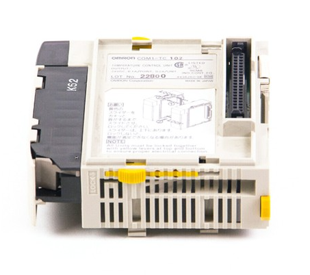 Omron CQM1-TC102 Temperature Control Unit
 -
 Omron CS1G-CPU65-EV1 CPU Unit CS1 Series
 -
 Omron CJ1H-CPU66H CPU Unit High Performance
 -
 Saia PCD4.H320 Analog Input Module
 -
 Omron NX-EIC202 EtherNet/IP Coupler Unit
 -
 Omron R88M-H75030 Servo Motor OMNUC Series 750W
 -
 Omron F500-VS Vision Sensor F500 Series Machine Vision
 -
 Omron R88S-H306G Power Unit for Servo Motor OMNUC Series
 -
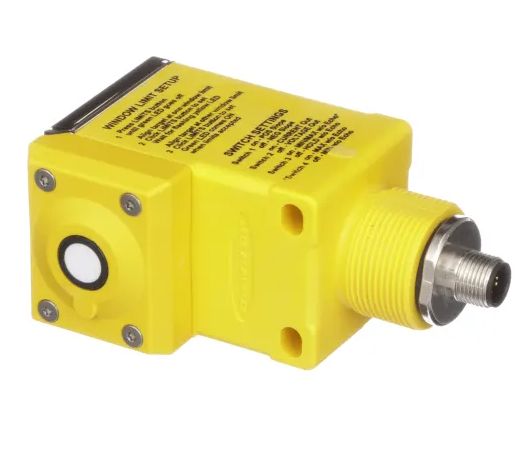 Banner Q45ULIU64ACR Ultrasonic Sensor Q45U Series Proximity Mode
 -
 Allen Bradley 1756-IRT8I RTD Thermocouple Input Module ControlLogix
 -
 Siemens Sinumerik 840D SL NCU 720.3B with PLC 317-3 PN DP
 -
 Kollmorgen SERVOSTAR J-06 Servo Drive Danaher Motion
 -
 Omron NX-ECC202 EtherCAT Coupler Unit NX Series
 -
 OMRON CS1W-SCU31-V1 Serial Unit
 -
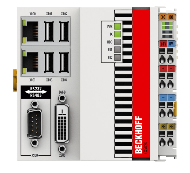 Beckhoff CX5020-0110 Embedded PC PLC
 -
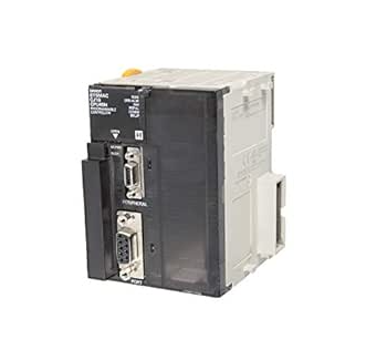
 Omron CJ1M-CPU13-ETN CPU Unit Ethernet
 -
 Omron C60H-C1DR-DE-V1 PLC Controller
 -
Omron CJ1W-PTS51 Thermocouple Input Unit
-
 Omron CJ1W-DA021 Analog Output Module 2 Ch
 -
 Omron CS1W-MAD44 Analog I/O Module
 -
 Omron C500-PRW05-V1 PROM Writer
 -
 Omron CJ1G-CPU45H Loop Control CPU Unit
 -
 ABB PSTX570-600-70 Soft Starter 570A
 -
 PTF Electronic SCR W1Z Power Controller 1150mm
 -
 Omron C500-CT012 High Speed Counter Unit
 -
 NBC Electronics MOD.ES 3 Ton Load Cell
 -
 DeltaOmega XML2 0060 45 4 S A Servo
 -
 REM EC235 Counter Module
 -
 Motor Power SKA DDR 148.30.8.19 Torque Motor
 -
 Delta Tau 4-Axis Interface PLC
 -
 Yokogawa PC10020 AA00 L1Z002 Position Controller
 -
 OMRON C60H-C5DR-DE-V1 PLC
 -
 Burgess PCD4.H320 Motion Control PLC
 -
 Parker SMB14245155242ID644 Servo Motor
 -
 Baumuller PLC-01 BMC-M-PLC-01-11-02 PLC
 -
 Omron CPM2B-32C2D1T-D12 PLC Compact Controller
 -
 Ansaldo SVTS076FBNF Industrial Drive 76KVA
 -
 Omron C500-PRW06 PROM Writer Programmer
 -
 Mitsubishi FX0N-24MR-ES PLC Compact Controller
 -
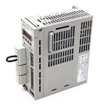
 Omron R88D-HS22 Servo Drive OMNUC H Series
 -
 Omron CJ1M-CPU11-ETN CPU Unit PLC
 -
 Bosch Rexroth 109129B051 HCP08 PLC Board
 -
 Landis Gyr PCD4.M125 PLC CPU Module
 -
 Nidec SP4202 Variable Frequency Drive 22kW
 -
 Puls QS40.241 Power Supply 40A 24VDC
 -
 Eaton XV-102-B6-35MQR-10-PLC Touch Panel
 -
 Omron ZFX-C15 Vision Sensor Controller
 -
 Kyosan PHS-4C-AN1 Servo Control Power Supply
 -
 Omron NX-ECC201 EtherCAT Coupler Unit
 -
 Omron C20-CPU83E CPU Unit 3G2C7-CPU83E
 -
 Omron FZ-SQ100F Vision Sensor Camera
 -
 Siemens 6SL3352-6BE00-0AA1 Power Supply Board
 -
 ABB AO815 3BSE052605R1 Analog Output Module
 -
 Siemens C98043-A1200-L Control Card
 -
 Allen-Bradley 1336-BDB-SP72D Gate Drive PCB
 -
 ST2000 34 Algorab Graphic PLC Terminal
 -
 OMRON C200HW-PRM21 Profibus DP Module
 -
 Siemens 2020964-001 DPM Base Board
 -
 OMRON CJ1W-V600C11 ID Controller Unit
 -
 Telemecanique TSX7 Series PLC Module
 -
 Okuma 1911-2861-0236049 Graphic Card Module
 -
 Parker HPD2S2N Servo Driver
 -
 OMRON FQ2-D31 Touch Finder Vision Sensor
 -
 OMRON C500-LK007 Host Link Unit
 -
 OMRON CJ1W-SCU32 Serial Communication Unit
 -
 Edwards C41901000 24V Solenoid Valve
 -
 ABB Procontic CS31 07 KR 91 PLC Controller
 -
 Siemens 7KG7750-0AA01-0AA0 Power Meter
 -
 Demag NC4K Compact PLC Controller
 -
 ABB SAPC 35 PAC/PP8482 Pulse Amplifier Board
 -
 Yaskawa SGMGH-09DCA6H-OY Servo Motor 850W
 -
 Saia PCD4.M445 Processor Module PLC
 -
 Yaskawa SGDH-04AE Servo Drive 400W 200V
 -
 Omron H8PR-24 Cam Positioner
 -
 Omron F150-C10E-2 Vision Sensor
 -
 OMRON 3G3MX2-A4015-E Inverter
 -
 Pro face GP577R-TC11 HMI
 -
 Pro face GP477R-EG11 HMI
 -
 ABB Pluto S20 V2 CFS Safety PLC
 -
 Siemens A5E00825002 IGD Board
 -
 Sakae SH40JHK-ZU-3S1R3G-10621B Joystick
 -
 Siemens 3RK1105-1AE04-0CA0 Safety Relay
 -
 Allen Bradley 1775-MEF Memory Module
 -
 OMRON CS1H-CPU63-H PLC CPU Unit
 -
 OMRON F150-C15E-3 Vision Sensor
 -
 Omron CJ1W-DA041 Analog Output Module
 -
 Saia PCD4.M440 PLC Module PCD4.M44
 -
 Steiel S595 PH Industrial Controller
 -
 VT650 PC Windows 2000 HMI Panel PC
 -
 Omron C200H-AD003 Analog Input Module
 -
 Omron CJ1W-V600C11 ID Sensor Unit
 -
 Coherent 250W Laser Adjustable Lens Head
 -
 Omron CQM1-AD042 Analog Input Module
 -
 SICK XKS09-HTBM-S02 Wire Draw Absolute Encoder
 -
 Omron 3F88L-P3A-E Cam Positioner PLC
 -
 OMRON R88M-H1K130 Servo Motor
 -
 SIEMENS 6ES7 331-7KB01-0AB0 SM331 Analog Input Module
 -
 LANDIS PCD4.M110 Processor Module
 -
 OMRON NT631C-ST151-EV2 HMI Touch Screen
 -
 TE.CO Grey Cable TFX 4G 1.5 ST 564mt UNEL Grey
 -
 OMRON R88D-H310G Servo Drive
 -
 ABB SACE SM3 630 630A PLC Switch
 -
 OMRON DRT2-AD04H Analog Input Terminal


