
GP477R Engineering Installation
Attention: The 12th and 13th pins are idle and must not be connected to any wires, otherwise it may damage the printer interface.
In practical engineering, due to the fact that modern printers are mostly USB or network interfaces, the frequency of use of this port is extremely low. If data recording is required, it is recommended to use a serial port external micro printer or forward the data to the upper computer through PLC.
AUX auxiliary interface (input/output)
The AUX interface is a 15 pin D-sub female socket that provides the following very practical external control and monitoring signals, which are very useful for integrating safety emergency stop circuits and equipment status indicators.
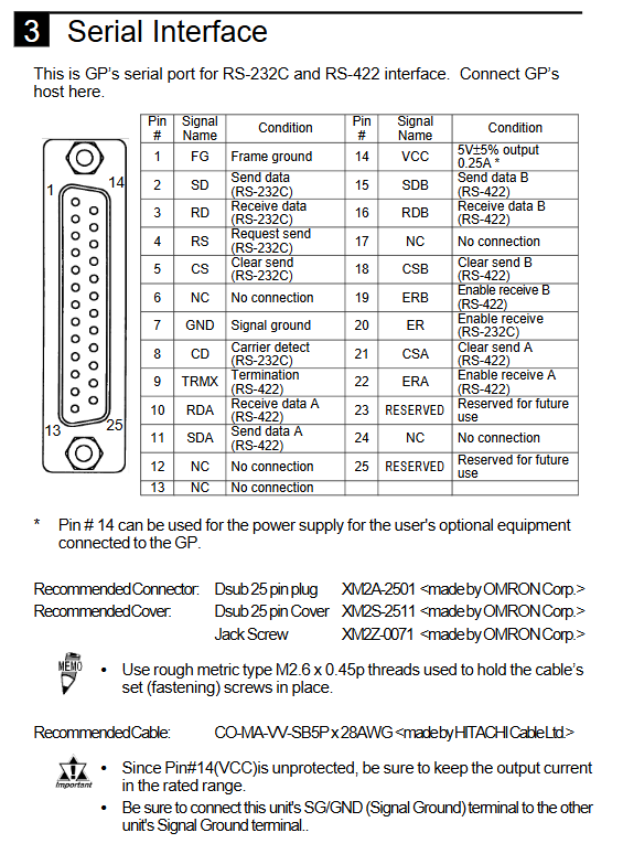
6.1 Pin List
Pin signal function description
1 TSW0 touch switch output (8-bit, TSW0~TSW7)
2 TSW1
3 TSW2
4 TSW3
5 TSW4
6 TSW5
7 TSW6
8 TSW7
9 RUN mode output: ON when GP is running; OFF when standby or power is off
10 ALARM alarm output: Conducted when a fatal hardware or software error occurs
11 BUZZ buzzer output: Follow the action of GP internal buzzer
12 DC24V output common terminal (DC24V side)
13 AIN-C input common terminal (DC24V side)
14 AOUT-C output common terminal (GND)
15 RESET reset input (low pulse effective)
6.2 Main application scenarios
Touch switch output (TSW0~7): When the user presses the specified touch switch on the screen, the corresponding transistor output will turn on. It can be directly used to control external indicator lights or relays, achieving "physical devices can be operated on the screen". These outputs are in the form of open collector and require an external pull-up resistor or DC load.
RUN output: can be used to light up a "running" indicator light when GP is running, or to interlock with PLC.
ALARM output: When GP detects serious faults such as screen memory verification errors or system errors, this output will be activated, thereby cutting off the main contactor or triggering the central alarm system.
Buzzer output: It can be connected in parallel with an external high-power buzzer to synchronously drive the external speaker when the GP emits a button sound or alarm sound.
Reset input (RESET): Short circuit the RESET pin (low level active) to AIN-C to reset the GP software, which is equivalent to powering on again. GP that can be used for remote reset of crashes.
When wiring, please distinguish the common terminal: use AOUT-C (GND) for the output circuit and AIN-C (DC24V) for the input circuit. We recommend using the OMRON XM2A-1501 plug, with the same screw specifications as the serial port M2.6.
Anti interference and signal line wiring
As a touch screen, GP477R is highly susceptible to electromagnetic interference from strong electrical devices such as frequency converters and contactors, resulting in communication interruption, touch misoperation, or display flickering. The following measures must be strictly implemented:
Separation of signal lines and power lines: All I/O signal lines (including serial ports, AUX, printers) must be routed separately from AC power lines, motor lines, and inverter output lines, with a minimum spacing of 20cm. If crossing is necessary, it should be done vertically instead of parallel.
Use shielded cables: Serial and AUX cables should use cables with total shielding and twisted pair structure. The shielding layer should be grounded at a single point at the GP end (connected to the FG terminal) and suspended at the opposite end to avoid ground current.
Grounding independence: The FG terminal of GP cannot be connected in series with the ground wire of the power equipment, and must be separately led to the grounding copper bar of the control cabinet. The grounding resistance should be less than 100 Ω, and if possible, it should be less than 10 Ω.
Surge protection: Connect a varistor (such as S14K275) in parallel at the power input end, or use a socket with filtering function.
Communication line length limit: RS-232C distance ≤ 15 meters, RS-422 ≤ 1200 meters (actual affected by baud rate). When exceeding the recommended distance, please use a repeater.
Summary of Safety Operations and Maintenance Suggestions
8.1 Safety principles that must be absolutely followed
No live plugging or unplugging: Before any operation of connecting or disconnecting cables, the GP power supply must be cut off. Otherwise, it may burn the port or cause electric shock.
Unauthorized disassembly is prohibited: GP has high-voltage circuits and lithium batteries (used for clock backup) inside. If lithium batteries are replaced incorrectly, there is a risk of explosion, and users cannot replace the batteries themselves. Please contact an authorized repair station when replacement is required.
External emergency stop: Virtual buttons on the touch screen must not be used for safety emergency stop functions. An independent mechanical emergency stop switch must be installed separately, and the main circuit cannot be directly controlled through GP.
Communication fault safety design: The control system should be able to detect communication interruptions between GP and PLC (such as through heartbeat signals) and put the machine into a safe state in case of a fault, rather than blindly executing the last instruction.
- ABB
- General Electric
- EMERSON
- Honeywell
- HIMA
- ALSTOM
- Rolls-Royce
- MOTOROLA
- Rockwell
- Siemens
- Woodward
- YOKOGAWA
- FOXBORO
- KOLLMORGEN
- MOOG
- KB
- YAMAHA
- BENDER
- TEKTRONIX
- Westinghouse
- AMAT
- AB
- XYCOM
- Yaskawa
- B&R
- Schneider
- Kongsberg
- NI
- WATLOW
- ProSoft
- SEW
- ADVANCED
- Reliance
- TRICONEX
- METSO
- MAN
- Advantest
- STUDER
- KONGSBERG
- DANAHER MOTION
- Bently
- Galil
- EATON
- MOLEX
- DEIF
- B&W
- ZYGO
- Aerotech
- DANFOSS
- Beijer
- Moxa
- Rexroth
- Johnson
- WAGO
- TOSHIBA
- BMCM
- SMC
- HITACHI
- HIRSCHMANN
- Application field
- XP POWER
- CTI
- TRICON
- STOBER
- Thinklogical
- Horner Automation
- Meggitt
- Fanuc
- Baldor
- SHINKAWA
- Other Brands
- UniOP
- KUKA
- Iba
-
 Omron C500-TU001 3G2A5-TU001 PLC Teaching Box
 -
 Saia PCD4.M110 PLC CPU Module Programmable Logic Controller
 -
 Yaskawa SGMPH-04AAA61D-OY Sigma-II AC Servo Motor 400W
 -
 Sumitomo Cyclo FAS35-119 Precision Cycloidal Gear Reducer
 -
 Omron IDSC-C1DR-A-E ID Controller PLC Unit
 -
 Omron F350-L100E OVL Image Processing Unit Vision System PLC
 -
 Omron CJ1W-F159 Load Cell Interface Weighing Module
 -
 Bticino MA250 T7314A250 Megatiker PLC Module
 -
 Mitsubishi AJ71QLP21G GI Fiber Optic Network Module
 -
 Omron R88D-HS10 Servo Drive DC Type
 -
 Omron FZ3-L355 Vision Sensor Controller
 -
 Omron C200H-CPU23-E CPU Unit PLC
 -
 Moeller UNIOP MI4-110-KG2 Text Display HMI
 -
 KEB COMBIVERT F5 07.F5.B1B-3B0A Inverter
 -
 Toshiba VFS15-4037PL-W Variable Frequency Drive
 -
 Omron CS1W-SCU31-V1 Serial Communication Unit
 -
 LSIS SV055iG5A-4 AC Drive 5.5kW
 -
Omron CJ1W-F159 Loadcell Interface Unit
-
 Omron CQM1-TC001 Temperature Control Module
 -
 Mitsubishi FX5-SF-MU4T5 Safety Module
 -
 Omron C1000H-CPU01-EV1 CPU Unit
 -
 Yaskawa SGDV-2R8A11A Servo Drive 400V
 -
 Omron 3G3HV-A4055-CUE VFD 5.5kW
 -
 Omron F160-C15E Vision Sensor Controller
 -
 Schneider ELAU PMC-2 Servo Drive 2.2kW
 -
 Omron CQM1-TC102 Temperature Control Unit
 -
 Omron CS1G-CPU65-EV1 CPU Unit CS1 Series
 -
 Omron CJ1H-CPU66H CPU Unit High Performance
 -
 Saia PCD4.H320 Analog Input Module
 -
 Omron NX-EIC202 EtherNet/IP Coupler Unit
 -
 Omron R88M-H75030 Servo Motor OMNUC Series 750W
 -
 Omron F500-VS Vision Sensor F500 Series Machine Vision
 -
 Omron R88S-H306G Power Unit for Servo Motor OMNUC Series
 -
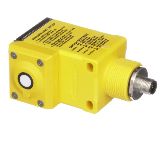 Banner Q45ULIU64ACR Ultrasonic Sensor Q45U Series Proximity Mode
 -
 Allen Bradley 1756-IRT8I RTD Thermocouple Input Module ControlLogix
 -
 Siemens Sinumerik 840D SL NCU 720.3B with PLC 317-3 PN DP
 -
 Kollmorgen SERVOSTAR J-06 Servo Drive Danaher Motion
 -
 Omron NX-ECC202 EtherCAT Coupler Unit NX Series
 -
 OMRON CS1W-SCU31-V1 Serial Unit
 -
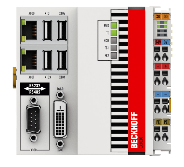 Beckhoff CX5020-0110 Embedded PC PLC
 -
 Omron CJ1M-CPU13-ETN CPU Unit Ethernet
 -
 Omron C60H-C1DR-DE-V1 PLC Controller
 -
Omron CJ1W-PTS51 Thermocouple Input Unit
-
 Omron CJ1W-DA021 Analog Output Module 2 Ch
 -
 Omron CS1W-MAD44 Analog I/O Module
 -
 Omron C500-PRW05-V1 PROM Writer
 -
 Omron CJ1G-CPU45H Loop Control CPU Unit
 -
 ABB PSTX570-600-70 Soft Starter 570A
 -
 PTF Electronic SCR W1Z Power Controller 1150mm
 -
 Omron C500-CT012 High Speed Counter Unit
 -
 NBC Electronics MOD.ES 3 Ton Load Cell
 -
 DeltaOmega XML2 0060 45 4 S A Servo
 -
 REM EC235 Counter Module
 -
 Motor Power SKA DDR 148.30.8.19 Torque Motor
 -
 Delta Tau 4-Axis Interface PLC
 -
 Yokogawa PC10020 AA00 L1Z002 Position Controller
 -
 OMRON C60H-C5DR-DE-V1 PLC
 -
 Burgess PCD4.H320 Motion Control PLC
 -
 Parker SMB14245155242ID644 Servo Motor
 -
 Baumuller PLC-01 BMC-M-PLC-01-11-02 PLC
 -
 Omron CPM2B-32C2D1T-D12 PLC Compact Controller
 -
 Ansaldo SVTS076FBNF Industrial Drive 76KVA
 -
 Omron C500-PRW06 PROM Writer Programmer
 -
 Mitsubishi FX0N-24MR-ES PLC Compact Controller
 -
 Omron R88D-HS22 Servo Drive OMNUC H Series
 -
 Omron CJ1M-CPU11-ETN CPU Unit PLC
 -
 Bosch Rexroth 109129B051 HCP08 PLC Board
 -
 Landis Gyr PCD4.M125 PLC CPU Module
 -
 Nidec SP4202 Variable Frequency Drive 22kW
 -
 Puls QS40.241 Power Supply 40A 24VDC
 -
 Eaton XV-102-B6-35MQR-10-PLC Touch Panel
 -
 Omron ZFX-C15 Vision Sensor Controller
 -
 Kyosan PHS-4C-AN1 Servo Control Power Supply
 -
 Omron NX-ECC201 EtherCAT Coupler Unit
 -
 Omron C20-CPU83E CPU Unit 3G2C7-CPU83E
 -
 Omron FZ-SQ100F Vision Sensor Camera
 -
 Siemens 6SL3352-6BE00-0AA1 Power Supply Board
 -
 ABB AO815 3BSE052605R1 Analog Output Module
 -
 Siemens C98043-A1200-L Control Card
 -
 Allen-Bradley 1336-BDB-SP72D Gate Drive PCB
 -
 ST2000 34 Algorab Graphic PLC Terminal
 -
 OMRON C200HW-PRM21 Profibus DP Module
 -
 Siemens 2020964-001 DPM Base Board
 -
 OMRON CJ1W-V600C11 ID Controller Unit
 -
 Telemecanique TSX7 Series PLC Module
 -
 Okuma 1911-2861-0236049 Graphic Card Module
 -
 Parker HPD2S2N Servo Driver
 -
 OMRON FQ2-D31 Touch Finder Vision Sensor
 -
 OMRON C500-LK007 Host Link Unit
 -
 OMRON CJ1W-SCU32 Serial Communication Unit
 -
 Edwards C41901000 24V Solenoid Valve
 -
 ABB Procontic CS31 07 KR 91 PLC Controller
 -
 Siemens 7KG7750-0AA01-0AA0 Power Meter
 -
 Demag NC4K Compact PLC Controller
 -
 ABB SAPC 35 PAC/PP8482 Pulse Amplifier Board
 -
 Yaskawa SGMGH-09DCA6H-OY Servo Motor 850W
 -
 Saia PCD4.M445 Processor Module PLC
 -
 Yaskawa SGDH-04AE Servo Drive 400W 200V
 -
 Omron H8PR-24 Cam Positioner
 -
 Omron F150-C10E-2 Vision Sensor
 -
 OMRON 3G3MX2-A4015-E Inverter
 -
 Pro face GP577R-TC11 HMI
 -
 Pro face GP477R-EG11 HMI
 -
 ABB Pluto S20 V2 CFS Safety PLC
 -
 Siemens A5E00825002 IGD Board
 -
 Sakae SH40JHK-ZU-3S1R3G-10621B Joystick
 -
 Siemens 3RK1105-1AE04-0CA0 Safety Relay
 -
 Allen Bradley 1775-MEF Memory Module
 -
 OMRON CS1H-CPU63-H PLC CPU Unit
 -
 OMRON F150-C15E-3 Vision Sensor
 -
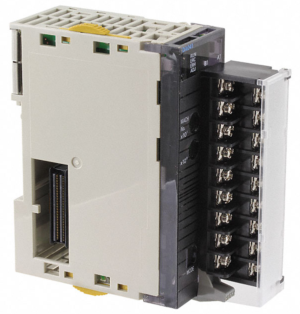 Omron CJ1W-DA041 Analog Output Module
 -
 Saia PCD4.M440 PLC Module PCD4.M44
 -
 Steiel S595 PH Industrial Controller
 -
 VT650 PC Windows 2000 HMI Panel PC
 -
 Omron C200H-AD003 Analog Input Module
 -
 Omron CJ1W-V600C11 ID Sensor Unit
 -
 Coherent 250W Laser Adjustable Lens Head
 -
 Omron CQM1-AD042 Analog Input Module
 -
 SICK XKS09-HTBM-S02 Wire Draw Absolute Encoder
 -
 Omron 3F88L-P3A-E Cam Positioner PLC
 -
 OMRON R88M-H1K130 Servo Motor
 -
 SIEMENS 6ES7 331-7KB01-0AB0 SM331 Analog Input Module
 -
 LANDIS PCD4.M110 Processor Module
 -
 OMRON NT631C-ST151-EV2 HMI Touch Screen
 -
 TE.CO Grey Cable TFX 4G 1.5 ST 564mt UNEL Grey
 -
 OMRON R88D-H310G Servo Drive
 -
 ABB SACE SM3 630 630A PLC Switch
 -
 OMRON DRT2-AD04H Analog Input Terminal


