
GE PACSystems RSTi EP EPSCPE100 Programmable Controller
GE PACSystems RSTi EP EPSCPE100 Programmable Controller
User characteristics
1 Controller Core Specifications
Main frequency: 1GHz
User memory: 1MB (configurable data and program memory, supports automatic positioning of symbolic variables)
I/O control capability: up to 2K I/O points
Reference table size:
Discrete quantity: 2k bits each for% I and% Q
Analog quantity: 2k words each for% AI and% AQ
Support batch memory (% W) for data exchange
Program blocks: Supports up to 512, with a maximum size of 128KB per block
Operating temperature range: -40 ° C to 70 ° C (-40 ° F to 158 ° F)
2 Operation and Instruction Components
Component Type Name Function Description
Short press the thin film run/stop button to switch CPU status (RUN/IO enabled) ↔ STOP/IO disabled); Default enabled, can be disabled in PME hardware configuration
LED indicator light OK (green) - always on: PLC diagnosed through power on and functions normally
-Extinguished: Not powered on or PLC malfunction
-Flashing (other LEDs off): PLC is in a stop/pause state, there may be a watchdog timer malfunction
LED indicator light RUN (green) - always on: PLC is in RUN mode
-Off: PLC is in STOP mode
-Flashing (other LEDs off): PLC encounters fatal error, flashing error code
LED indicator light FAULT (green) - always on: PLC is in stop/fault mode, fatal fault has occurred
-Extinguish: No fatal malfunction detected
Ethernet LED for each RJ-45 port (yellow/green) - Green: Ethernet connection established
-Yellow: There is packet transmission present
3 Ethernet Port Configuration
Number of port categories, functional characteristics, default network parameters
LAN1: 1 non switching, dedicated to high-speed Ethernet; Support communication with PME software via SRTP protocol IP: 192.168.0.100
Subnet mask: 255.255.255.0
Gateway: 0.0.0.0
LAN2 with 3 switch ports; Can be configured as an embedded Ethernet controller or PROFINET controller (supports simplex mode only) IP: 0.0.0.0
Subnet Mask: 0.0.0.0
Gateway: 0.0.0.0 (requires a valid IP configuration to be available)
4 Communication Capability
Server connection: Up to 16 SRTP+Modbus TCP combination connections (Modbus TCP not exceeding 8), or 16 SRTP connections, or 8 Modbus TCP connections
Client connections: up to 8, supporting SRTP, Modbus TCP, or a combination of both
EGD exchange: up to 8 simultaneous Type 1 Ethernet global data exchanges
Optimal performance combination: Server (Modbus/RTP) ≤ 4 channels, Client (Modbus/RTP) ≤ 4 channels, PROFINET nodes ≤ 8, EGD exchange ≤ 8

Hardware installation
1 Initial Inspection
Check if the shipping container is damaged. If damaged, immediately notify the carrier and keep the container as evidence
Record all serial numbers after unpacking (to be provided during warranty)
Check if the received components match the order, if not, contact customer service
Retain all packaging materials for future transportation
2 Installation location and method
2.1 Requirements for installation clearance
Left and right sides: minimum 50mm
Upper and lower sides: minimum 100mm (meets heat dissipation requirements)
2.2 DIN rail installation (default method)
Tilt the device so that the upper hook of the DIN rail adapter engages with the upper edge of the rail
Press the lower part of the device and hear a "click" sound, indicating that the lower hook is engaged with the lower edge of the guide rail (no additional tools required)
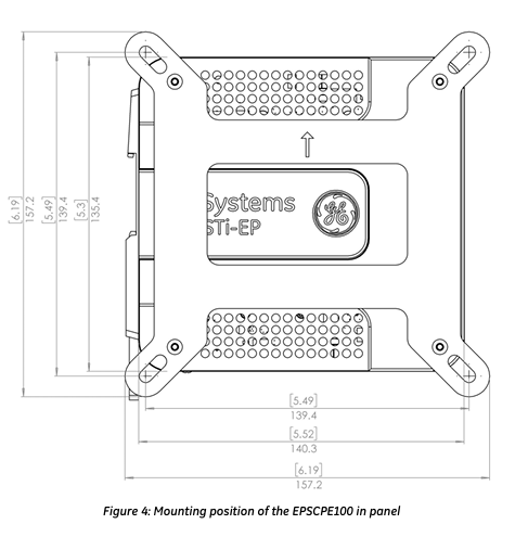
2.3 Panel installation (optional, requires adapter ICMFAACC001-AA)
Secure the panel mounting plate to the back of CPE100 using the 4 M3 screws provided with the adapter
Fix the protruding ears of the panel installation adapter in the corresponding position on the panel with 4 screws (size not exceeding M5)
Screw torque: When installing the adapter, it needs to be tightened to 5.3 in Ibs (0.6 Nm)
2.3 Grounding Requirements
Connect the grounding terminal of CPE100 to the DIN rail using 16-22 AWG braided wire (with terminal block)
DIN rails need to be grounded according to the instructions in the RSTi EP System Manual (GFK-2958)
Module startup
1 Required items for startup
PACSystems RSTi EP CPE100 Controller
Power supply: 9-30V DC, 5W output (must be a Class II power supply, labeled as "double insulated", "limited power supply (LPS)" or SELV power supply, and must have a minimum 32V DC and maximum 3A fuse)
Installation carrier: DIN rail (usually installed inside the cabinet) or optional panel mounting adapter (ICMFAACC001-AA)
Computer: Installed with Proficy Machine Edition (PME) software (version ≥ 9.50 SIM 1)
Ethernet cable: used to connect a computer to CPE100
Screwdriver: 1.4mm size (jeweler's specification, used for terminal operation)
2 Basic installation steps
Ensure that CPE100 is powered off
Choose DIN rail or panel installation method to fix CPE100
Connect power supply:
Wire specification: 22-16 AWG (copper wire, temperature rating 80 ° C)
Wiring length: not exceeding 30 meters
Screw torque: 2 in Ib
Connect Ethernet cable:
LAN1 port: connects computers for programming and protocols (SRTP, Modbus, EGD)
LAN1 port (if required): Connect to PROFINET network (there may be a typographical error in this document, combined with the previous text, it should be LAN2 port, subject to actual configuration)
Power on CPE100
Programming Configuration (EPSCPE100)
1 Basic Programming Requirements
Software version: PME 9.50 SIM 1 and above
Connection method: Connect the computer to CPE100 through LAN1 port, using the default IP address (192.168.0.100)
2 Project Creation and Conversion
New Project: Use the "RSTi-EP CPE100" Template
Existing project conversion: Convert other PLC projects to CPE100 projects through PME's "family conversion" function (constraints should be noted during conversion, such as the first PROFINET controller in the RX3i CPU320 application being assigned to the embedded PROFINET controller function of CPE100)
5.3 PROFINET Controller Configuration
Select the CPE100 target device in the PME navigator and open 'Hardware Configuration'
In the "Settings" tab, change the "Mode" of the LAN2 port to "PROFINET"
After configuration is complete, the PROFINET controller node description will display the existence of PROFINET nodes on the corresponding LAN (refer to the PACSystems RX3i&RSTi EP PROFINET IO Controller User Manual GFK-2571 for detailed operation)
Firmware upgrade process
1 Preconditions for Upgrade
Connection port: Use LAN1 port (default IP 192.168.0.100, can be modified through PME)
Controller status: Set to "stop disabled" mode (operated through programming software or run/stop switch)
PC settings: If using a proxy server, you need to modify the network settings to disable the proxy or automatically configure the proxy script
Firmware file: Download the latest PAC format firmware file from the GE support website (it is recommended to check for a new version before upgrading)
2 Upgrade Steps
Copy the firmware upgrade file (PAC format) to any directory on the computer
Open the browser and enter the programming communication IP of CPE100 (such as http://192.168.0.100 )Enter the homepage
Login: username "update", password "sierra" (both without quotation marks)
Click on 'Select File', find and select the copied PAC file, and then click 'Open'
Click on 'Upload File' and wait for the upload progress to complete (the upgrade process takes up to 4 minutes, during which power off is prohibited, otherwise the device may not be able to recover)
After the upgrade is completed, CPE100 will automatically reset, and the browser will display the "DONE" status to indicate success; If it fails, an error status will be displayed
After successful upgrade:
Close browser window
Mark the new firmware version on CPE100 (the label cannot cover the ventilation opening)
Restore CPE100 to 'Run Enable' mode through programming software
Product Restrictions (Release 1.0 Version)
Does not support MRP (Media Redundancy Protocol)
Not supporting C Toolkit
Cannot support timed interrupt blocks
RDSD is not supported
Troubleshooting
IP Address Reset and Device Recovery
Applicable scenarios: IP needs to be restored to default value (192.168.0.100), or the device is in an unknown state
Operation steps: When CPE100 is powered on, press and hold the "Run/Stop" button until the device is fully powered on (about 60 seconds)
Effect: IP address restored to 192.168.0.100, while clearing the contents of Flash and RAM

- OMRON
- ABB
- General Electric
- EMERSON
- Honeywell
- HIMA
- ALSTOM
- Rolls-Royce
- MOTOROLA
- Rockwell
- Siemens
- Woodward
- YOKOGAWA
- FOXBORO
- KOLLMORGEN
- MOOG
- KB
- YAMAHA
- BENDER
- TEKTRONIX
- Westinghouse
- AMAT
- AB
- XYCOM
- Yaskawa
- B&R
- Schneider
- KONGSBERG
- NI
- WATLOW
- ProSoft
- SEW
- ADVANCED
- Reliance
- TRICONEX
- METSO
- MAN
- Advantest
- STUDER
- DANAHER MOTION
- Bently
- Galil
- EATON
- MOLEX
- DEIF
- B&W
- ZYGO
- Aerotech
- DANFOSS
- Beijer
- Moxa
- Rexroth
- Johnson
- WAGO
- TOSHIBA
- BMCM
- SMC
- HITACHI
- HIRSCHMANN
- Application field
- XP POWER
- CTI
- TRICON
- STOBER
- Thinklogical
- Horner Automation
- Meggitt
- Fanuc
- Baldor
- SHINKAWA
- Other Brands
- UniOP
- KUKA
- Iba
- Beckhoff
- ADLINK
-
 Basler Electric 9289902106 Circuit Board
 -
 Basler Electric BE1-32R Protective Relay A1E E1P BOS1P
 -
 Basler Electric RAL6144-16GM GigE Line Scan Camera with Lens
 -
 Basler Electric BE3-49R-5I5A1 Temperature Relay
 -
 Basler Electric BE1-32R Power Relay B3E E1R A0N1F
 -
 Basler Electric SR4A2B06B3A Static Voltage Regulator Features
 -
 Basler Electric 9121000106 Manual Voltage Control MVC Guide
 -
 Basler Electric SR32A-2B15B3E Static Voltage Regulator
 -
 Basler Electric SR4A2B06B3A Static Voltage Regulator Guide
 -
 Basler Electric 801A193F02 Hammond Transformer Module
 -
 Basler Electric BE1-24 Volts Per Hertz Relay A1E F1J D1S0F
 -
 Basler Electric AEC63-7 Analog Excitation Controller 220-277V
 -
Basler Electric BE132R Power Relay T245579
-
 Basler Electric MVC 108 Manual Voltage Control 90 37000 102
 -
 Basler Electric 9022900-103 Control Transformer 6-7VA 60Hz
 -
 Basler Electric BE1-79M Plug Adapter 9170111102
 -
 Basler Electric 9 2007 00 100 Current Boost System CBS 305
 -
 Basler Electric SR4A2B01B3A Static Voltage Regulator 120V
 -
Basler Electric BE1-32R Power Solid State Relay E2E A10 A0N0F
-
 Basler Electric PRS250 Veri-Sync Relay 9088800102
 -
 Basler DECS 125-15-B2C Digital Excitation Control
 -
 Basler BE 13693 002 Transformer
 -
Basler BE1-59N Ground Fault Overvoltage Relay
-
 Basler BE1-79A Reclosing Relay
 -
 Basler 9-1051-00-105 Overload Protection Module
 -
 Basler BE1-32R Power Relay – Directional Overcurrent Guide
 -
 Basler 9319700103 BE3-27T/59T-3A1N3 Voltage Relay
 -
 Basler BE1-87G Generator Differential Relay
 -
 Basler BE3-25-1D1N4 9319100106 480V Relay
 -
 Basler SR8A2B07B3A Static Voltage Regulator
 -
 Basler Electric BE4-27/59 Over/Under Voltage Relay 307-2552
 -
Basler Electric SR32A2B05B3E Static Voltage Regulator
-
Basler Electric BE1-27 A3E C3J A1N6F Solid State Protective Relay
-
 Basler Electric 9174700-100 Excitation Limiter Generator
 -
 Basler Electric BE1-87G Generator Differential Relay 09833
 -
 Basler Electric 9310200100 Power Supply Module
 -
 Basler Electric TIEE1CD0N07 Control Module
 -
Basler Electric BE1-59N Ground Fault Relay T214750
-
Basler Electric SR8A2B10B3AX Static Voltage Regulator 9060200126
-
 Basler Electric SSR 125-12 Voltage Regulator
 -
 Rolls Royce H1111.0204 Ship Main Controller
 -
 Basler Electric BE3-32-3AC Reverse Power Relay 9 1376 00 105
 -
Basler Electric BE3-25-1A1N4 Synch Check Relay 9319100100
-
 Basler Electric SR4A-2B15B3A Static Voltage Regulator
 -
 Basler Electric SR4A-2B15B3E Static Voltage Regulator
 -
 Basler Electric 9170818100 Solid State Protective Relay
 -
 Basler Electric AEC63-7 Analog Excitation Controller
 -
 Basler Electric 17483 Auxiliary Module
 -
Basler Electric BE1-59 Over Voltage Relay
-
Basler Electric 21600-101 Control Module
-
 Basler Electric KR2F Generator Voltage Regulator 9056600100
 -
 Basler BE1-CDS Current Differential System
 -
 Basler Electric CBS 212 Current Boost System 9 2650 00 100
 -
 Basler Electric IFM-150 Firing Circuit Chassis
 -
 Basler Electric BE1-60 Voltage Balance Relay C1F A1P D0C3F
 -
Basler Electric BE1-32R Power Relay A2E D1R A0N0F
-
Basler Electric BE1-32R Power Relay A2E D1R A0N0F
-
 Basler Electric 8650C80G01 Isolation Transducer PCB Board
 -
 ETEL EA-P2M-300-4/7.5A-0100-01 AccurET Modular 300 Servo Drive
 -
 Basler Electric 87T Transformer Differential Relay
 -
Basler Electric BE-6868 Power Transformer 5950007559202
-
 Basler Electric PRS250 Veri-Sync Relay 9088800102
 -
 Basler Electric SCP-250-G-60 VAR Power Factor Controller
 -
 Basler DECS-150 AVR 1NS2V1N1S Voltage Regulator
 -
Basler UFOV 260A Under Frequency Overvoltage Module
-
 Basler MOC2 199 Motor Operated Control – Overview and Setup
 -
 Basler BE3-49R-5K5A1 Temperature Relay – Complete Guide
 -
Basler BE 20035 001 Transformer – Technical Data and Installation
-
 Basler BE 02727 001 Transformer – Specifications and Usage
 -
 Basler BE127 Under Voltage Relay – Features and Application Guide
 -
Basler CBS377 Current Boost System – Complete Technical Guide
-
Basler BE1-87G P/N 9170818100 Differential Relay – In-Depth Specs
-
Basler BE1-87G Generator Differential Relay – Technical Overview
-
Basler Electric SR4A2B16 SVR Static Voltage Regulator – Complete Guide
-
 Basler Electric 9261500101 Power Supply Module
 -
 Basler Electric AEM-2020 Analog Expansion Module
 -
Basler Electric DGC-2020 Digital Genset Controller 51BRBNEAH001
-
Basler Electric BE1-59N Ground Fault Overvoltage Relay
-
Basler Electric BE1-59N-A5E-E1L-N0S1F Neutral Overvoltage Relay
-
Basler Electric MOC2499 Motor Operator Control Potentiometer 9072300430
-
 Basler Electric BE1-50/51M Overcurrent Relay
 -
 Basler Electric 9148100106 MOC3502 Solid State Relay 250VDC 0.25A
 -
 Basler Electric CBS 212 Current Boost System 9265000100
 -
Basler Electric 10493002 Control Module
-
Basler BE1-32R D3E E1R A0N1F Power Relay
-
 Basler SR8A2B15B3A Static Voltage Regulator
 -
 Basler IFM-105 Firing Circuit Chassis 9324100105
 -
Basler SR4A2B05B3A Static Voltage Regulator
-
 Basler BE151G1EB6PB0N0F Protective Relay
 -
Basler BE1-59 Electric Over Voltage Relay
-
 Basler 277 Static Programmable Powerline Carrier Channel
 -
Basler BE1-32R D1E A1P A0N1F Power Relay
-
Basler SR4A1B07B3A Static Voltage Regulator
-
 Basler Electric BE1-700 Digital Protective Relay
 -
Basler Electric SR8A-2B01B3A Static Voltage Regulator
-
Basler Electric SR4A-2B01B3E Static Voltage Regulator
-
Basler Electric 9017709102 PC Board
-
Basler Electric SR4A-2B01B3A Static Voltage Regulator
-
Basler Electric PRS-250 Veri-Sync Relay
-
 Basler Electric 9066800102 Excitation Support System
 -
Basler Electric BE1-87G Generator Differential Relay 9 1708 18 100
-
 Basler Electric 36T865-2 BE03752001 Power Supply
 -
 Basler Electric M-300 149D940G02 Power Supply
 -
 Basler Electric ACA2040-25GM 4Mp 25Fps Area Scan Camera
 -
 Basler BE1-87G-S1A-A1C-A0N0 Differential Relay
 -
Basler SR8A-2B06B3E Static Regulator SR8A2B06B3E
-
 Basler SCP-210 Frequency Controller 9095400100
 -
 Basler BE1-59-A3E-A1J-N1N3F Overvoltage Relay BE159A3EA1JN1N3F
 -
Basler 9 2011 11 100 Bracket Mounted Terminal Unit
-
Basler 9 1606 00 101 Voltage Regulator
-
 Basler CBS-377 Current Boost System 9109600102
 -
Basler 8650C72 Exciter Control Module PCB Rev 5
-
Basler C2EE1PA0N1F BE1-32R Reverse Power Relay
-
 ADLINK HPCI-14S12U - Industrial Control Backplane 12PCI Backplane PCI-14S Passive Backplane
 -
-0010.png) ADLINK PCIe-GIE74C - image acquisition card 4-CH GigE Vision PoE+ Frame Grabber
ADLINK PCIe-GIE74C - image acquisition card 4-CH GigE Vision PoE+ Frame Grabber -
-0010_1.png) ADLINK PCI-8164 - control card 4-Axis Advanced Motion Controller Board
ADLINK PCI-8164 - control card 4-Axis Advanced Motion Controller Board -
 ADLINK PCIe-U304 - 4 Port USB3 PCIe Frame Grabbers USB Screw Hole Card
 -
 ADLINK PCI-9112 - Multi-Function Data Acquisition Card DAQ Card
 -
 ADLINK PCI-7432 - 51-12013-0A50 4-CH Isolated Numérique I/O PCI Cartes Digital I/O Card
 -
 ADLINK PCA-6106P3-0C1 REV.C1 - backplane 6-Slot Passive Backplane Board
 -
 ADLINK PCI-7224 - 24-CH Opto-Isolated Digital I/O PCI Board
 -
 ADLINK CPCI-7433R(G) - Digital Input Board Rear I/O CompactPCI Card
 -
 ADLINK EBP-13E4 - 51-46703-0A30 Industrial PC Backplane Passive Backplane
 -
 ADLINK PCIE-HDV62 - Image acquisition card High Definition Video Frame Grabber
 -
 ADLINK EBP-13E4 - 51-46703-0A30 Industrial Backplane Board Passive Backplane
 -
 ADLINK 90111-B1 / CPCI-6770 - PCB CPU MODULE CompactPCI Single Board Computer
 -
 ADLINK PCI-7248 - DATA ACQUISITION PCI CARD 48-CH Parallel Digital I/O Board
 -
 ADLINK PCI-7230 - 51-12003-0a50 board PCI7230 32-CH Isolated Digital I/O Card


