MKS Type T3B Butterfly Valve (with DeviceNet Interface)
Symbols on equipment: including power on/off (IEC 417 No.5007/5008), grounding (IEC 417 No.5017/5019/5020/5021), AC/DC (IEC 417 No.5031/5032/5033-a), Class II equipment (IEC 417 No.5172-a), three-phase AC (IEC 617-2 No.020206), hand compression risk (ISO 3864), electric shock risk (ISO 3864 No.B.3.6), etc. The manual provides detailed explanations of the meanings of each symbol in table form.
Installation environment and location
Environmental requirements: The working temperature range is 20 ° C-40 ° C, the working humidity is 0% -95% (non condensing), and the storage temperature range is -20 ° C-80 ° C.
Installation position: It can be installed on the vacuum exhaust pipeline (with suitable joints). To achieve optimal pressure control, the pressure sensor and T3B should be as close to the process chamber as possible to reduce the time constant; The connecting pipe between the sensor and the chamber should be less than 6 inches and have a diameter of not less than 1/4 inch. If it exceeds 6 inches, a larger diameter pipe should be used to compensate for the conductivity loss.
System configuration and electrical connections
Typical configuration: The system includes a DeviceNet network host (sending set values, receiving pressure/position/diagnostic data), a 24 VDC valve power supply, a sensor power supply (optional ± 15 VDC), a T3B unit, an analog Baratron sensor, and an alarm relay output that can be connected to external alarm devices.
Grounding requirements: If power is taken from the DeviceNet network, it must comply with the grounding requirements of the ODVA DeviceNet specification (Volume I).
Definition of connector pins:
Digital communication connector (5-pin): 1-pin (Drain), 2-pin (V+), 3-pin (V -), 4-pin (CAN_S), 5-pin (CAN_L).
Auxiliary connector (25 pins): includes receive data (RX), send data (TX), pressure output (A Out), position output (A Out), 2 sets of relays (normally open/normally closed/common terminal), valve open/closed status (digital output), interlock (digital input), analog ground, digital ground, chassis ground, etc. Pins 11-13 are related to analog signals, pins 14-19 are relays, pins 20-22 are digital status and input, and pins 24-25 are ground.
Analog sensor connector (15 pins, with the same high and low sensor pins): 2-pin (pressure input+), 5-pin (sensor power return), 6-pin (-15 V), 7-pin (+15 V), 12 pin (pressure input -), 14 pin (+24 V power output), 15 pin (chassis ground), with no other pins connected.
External power connector (9-pin): 1-2 pins (+24 V input), 3-4 pins (24 V return), 5-pin (+15 V auxiliary input, for instruments), 6-pin (15 V return), 7-pin (-15 V auxiliary input, for instruments), 8-pin (reserved), 9-pin (chassis ground).
startup process
Power on sequence: First supply power to the DeviceNet network, then supply power to T3B; When powered on, the device checks the communication link, EEPROM, and RAM internal diagnostics, and the results are indicated by the top status LED (color and flashing status).
LED startup sequence: The module status LED flashes alternately green and red for about 0.25 seconds each before turning green; The network status LED flashes alternately in green and red for about 0.25 seconds each before turning off; After initialization is completed, the module status LED remains constantly green; When there are no other network devices, the network status LED remains off; When there are other devices, the network LED flashes green during repeated MAC checks and before establishing a connection.
Preheating time: After installation and power on, the preheating time of the controller is less than 1 minute.

Operation Guide
Operation Mode
User mode: default power on mode, which is the normal operation mode.
Calibration mode: used to access specific calibration and operating parameters. The device functions are the same in both modes, but network access to certain attributes may be restricted (refer to the object attribute table in the supplementary manual for specific permissions).
Communication Configuration
Baud rate and MAC ID settings: can be set through software (DeviceNet protocol network command) or manually (top rotary switch). When powered on, if the switch is in the "PGM" position, the baud rate/address can be read from non-volatile memory, and the network can modify parameters. Changes in the switch position require a power outage and restart to take effect; If the switch is not in the "PGM" position and the switch value is directly read, the network modification request is rejected and an error code of "Attribute_Cot_Settable" is returned.
Communication specifications: Supports 125/250/500 Kbps baud rates; The network topology is linear (trunk/branch), with power and signals sharing the same cable; Supports up to 64 nodes; Explicit message communication delay<50 milliseconds (average<25 milliseconds), I/O polling message delay<4.5 milliseconds (average<1.5 milliseconds); Equipped with module status (green/red) and network status (green/red) LED indicators.
Core operational functions
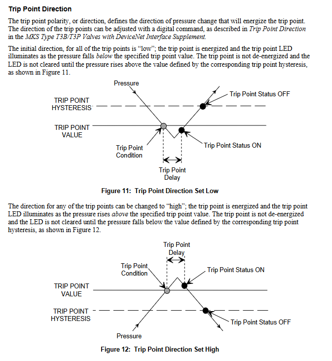
Parameter setting and monitoring: Through the DeviceNet network, set values (pressure/position), valve direction (forward/reverse), pressure values and units, valve position, trip point values/hysteresis/delay/status can be set and reported, monitoring system status, reporting operating time, and setting valve soft start; Storage device identification information (manufacturer information, model serial number, factory calibration data, software and hardware version number).
- ABB
- General Electric
- EMERSON
- Honeywell
- HIMA
- ALSTOM
- Rolls-Royce
- MOTOROLA
- Rockwell
- Siemens
- Woodward
- YOKOGAWA
- FOXBORO
- KOLLMORGEN
- MOOG
- KB
- YAMAHA
- BENDER
- TEKTRONIX
- Westinghouse
- AMAT
- AB
- XYCOM
- Yaskawa
- B&R
- Schneider
- Kongsberg
- NI
- WATLOW
- ProSoft
- SEW
- ADVANCED
- Reliance
- TRICONEX
- METSO
- MAN
- Advantest
- STUDER
- KONGSBERG
- DANAHER MOTION
- Bently
- Galil
- EATON
- MOLEX
- Triconex
- DEIF
- B&W
- ZYGO
- Aerotech
- DANFOSS
- Beijer
- Moxa
- Rexroth
- Johnson
- WAGO
- TOSHIBA
- BMCM
- SMC
- HITACHI
- HIRSCHMANN
- Application field
- XP POWER
- CTI
- TRICON
- STOBER
- Thinklogical
- Horner Automation
- Meggitt
- Fanuc
- Baldor


