
TEKTRONIX CFG 253 Function Generator
TEKTRONIX CFG 253 Function Generator
Basic and Product Positioning
The official user manual for Tektronix CFG253 function generator (model 070-8362-04) states that the core purpose of the device is to generate various standard waveforms for audio equipment testing, ultrasound equipment calibration, servo system debugging, and other scenarios. It supports flexible adjustment of amplitude, frequency, waveform symmetry, as well as internal/external sweep functions to meet different testing needs.
Core parameters and functions
1. Key Electrical Characteristics
Parameter Category Specific Indicator Remarks
Normal frequency range (Freq/1): 0.3 Hz-3 MHz (7-speed RANGE: 1/10/100 Hz, 1/10/100 KHz, 1 MHz); 10 frequency division (Freq/10): 0.03 Hz -300 KHz Frequency accuracy: ± 5% Full scale (applicable to both normal and 10 frequency division)
Waveform types: sine wave, square wave, sawtooth wave, TTL synchronization signal. TTL signal is output from SYNC OUTPUT with fixed parameters
There are two selectable main output amplitudes (VOLTS OUT button switch):
1. Pop up mode: 0-20 V ₚₚ (open circuit), 0-10 V ₚₚ (50 Ω load)
2. Press the gear: 0-2 V ₚₚ (open circuit), 0-1 V ₚₚ (50 Ω load). The amplitude is continuously adjusted by the AMPLITUDE knob
DC offset ± 10 V (open circuit), ± 5 V (50 Ω load) Pull the DC OFFSET knob to activate, and when pressed, the offset is 0
Waveform quality sine wave distortion:<1% (10 Hz-100 KHz); Square wave rise/fall time: ≤ 100 ns (50 Ω load); Sawtooth wave linearity: ≥ 99% (20 Hz-200 KHz), ≥ 97% (200 KHz -3 MHz)-
Internal frequency scanning function: rate 0.5-50 Hz (SWEEP RATE adjustment), width 1:1-100:1 (SWEEP WIDTH adjustment); External sweep frequency: VCF INPUT input 0-+10 VDC, sweep frequency range 2 times (100:1). When performing external sweep frequency, the SWEEP button needs to pop up
2. Physical parameters
Specific indicators for parameter categories
Dimensions: Width 240 mm (9.46 in), Height 64 mm (2.53 in), Depth 230 mm (9.0 in)
Weight 2.0 kg (4.4 lb)
Safe operation and initialization
1. Safety regulations (must be followed)
Grounding requirements: The equipment should be grounded through the grounding conductor of the power cord. It is forbidden to remove the grounding pin of the power cord, otherwise it may cause electric shock; Before connecting the signal, it is necessary to confirm that the device is reliably grounded.
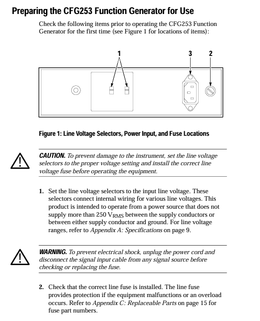
Line voltage and fuse:
The line voltage needs to be set to the appropriate value (supporting 4 levels: 90-110/108-132/198-242/216-250 VAC, 50-60 Hz). Setting it incorrectly can burn out the equipment;
Fuses need to be matched according to voltage: 0.3 A, 250 V, 3AG specifications (part number 159-0029-00) are used for 90-132 V operation, and 0.15 A, 250 V, 3AG specifications (part number 159-0054-00) are used for 198-250 V operation. Before replacement, the power must be turned off and the signal input disconnected.
Interface limitation: The VCF INPUT input voltage of the rear panel can reach a maximum of ± 10 V ₚₖ. Exceeding this range may damage the internal circuit.
Environmental taboos: Do not operate in damp or explosive environments; Do not operate with the cover open (as it may come into contact with high-voltage components, causing electric shock or fire).
2. Initialization operation steps
Set line voltage: Adjust the equipment line voltage selector (position shown in Figure 1) according to the local power supply voltage to ensure it matches the power supply voltage.
Check the fuse: Open the fuse cover and confirm that the installed fuse specifications are compatible with the line voltage. If the specifications are incorrect, replace it.
Connect power supply: Use the device's designated power cord (standard configuration is 115V North American model, other regions require corresponding accessories, refer to Table 7), and plug it into a grounded power outlet.
Power on check: Press the POWER button, confirm that the POWER On Light is on, and the device enters standby mode.
Panel controls and interface functions
1. Front panel controls (Figure 2)
Control Number Control Name/Function Operation Instructions
1 POWER ON Light indicator light on → Device powered on, off → Power off or malfunction (such as blown fuse)
2 AMPLITUDE knob adjusts the amplitude of the main output signal, with the range determined by the VOLTS OUT button (0-2 V ₚₚ or 0-20 V ₚₚ)
Press the 3 DC OFFSET knob → DC offset is 0; Pull on → Adjust the DC level of the main output signal (range ± 10 V open circuit)
The SYMMETRY knob only takes effect when the SYMMETRY button is pressed: adjust the square wave duty cycle, sawtooth wave/sine wave rise and fall time
5 RANGE (Hz) button (7 levels: 1/10/100 Hz, 1/10/100 KHz, 1 MHz) to select the frequency range, such as pressing "1 K" → frequency range 0.3 KHz -3.0 KHz
Press the corresponding button (sine wave/square wave/sawtooth wave) to select the desired waveform for the main output
Within the selected range of the RANGE button, continuously fine tune the output frequency with the 7 FREQUEncy knob
The 8 SWEEP WIDTH knob only takes effect when the SWEEP button is pressed internally: adjust the sweep amplitude (1:1-100:1)
The 9 SWEEP RATE knob only works when scanning internally: adjust the scanning rate (0.5-50 Hz)
Press the 10 SWEEP button → Enable internal sweep frequency; Pop up → Enable external sweep (controlled through VCF INPUT)
Press the SYMMETRY button → Output frequency ÷ 10, and activate the SYMMETRY knob function at the same time; Pop up → Normal frequency, knob failure
Press the 12 VOLTS OUT button → amplitude range 0-2 V ₚₚ (50 Ω load 0-1 V ₚₚ); Pop up → amplitude range 0-20 V ₚₚ (50 Ω load 0-10 V ₚₚ)
13 SYNC (TTL) OUTPUT (BNC interface) outputs TTL synchronization signal with fixed amplitude and DC offset (not affected by AMPLITUDE/DC OFFSET knob)
14 MAIN OUTPUT (BNC interface) outputs sine wave/square wave/sawtooth wave signals, with parameters adjusted by corresponding controls
Press the POWER button to turn on the device; Press again → Shut down
2. Rear panel interface (Figure 3)
Interface Name Function Description
VCF INPUT (BNC) external sweep frequency input interface: Input 0-+10 VDC signal, control the main output frequency sweep (range of 2 times ten)
Core Function Operation Guide
1. TTL signal generation
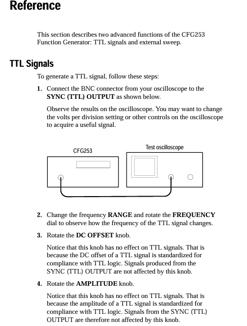
The TTL signal parameters (amplitude, DC offset) comply with the TTL standard and cannot be adjusted. The operation steps are as follows:
Connect the oscilloscope input to the SYNC (TTL) OUTPUT interface of CFG 253 using a BNC cable;
Press the POWER button to turn on the device, use the RANGE button to select the frequency range, and rotate the FREQUEncy knob to fine tune the frequency;
Observe oscilloscope waveform: Rotate the DC OFFSET or AMPLITUDE knob, and the waveform remains unchanged (TTL signal parameters are fixed).
2. External frequency scanning operation
External frequency scanning requires controlling the scanning parameters through an external voltage source. The steps are as follows:
Connect the MAIN OUTPUT of CFG253 to the oscilloscope input using a BNC cable, and connect the external voltage source to the VCF INPUT (rear panel) of CFG253 using a BNC cable;
Rotate the SWITCHY knob to the "0.3" position (ensuring that the sweep range covers the required area);
Pop up SWEEP button (turn off internal sweep and enable external control);
Adjust the output of the external voltage source (0-+10 VDC), and observe the frequency change of the main output with an oscilloscope: voltage increase → frequency decrease, voltage decrease → frequency increase, with a sweep frequency range of 2 harmonics (100:1).
3. Adjustment of waveform symmetry
Symmetry adjustment can change the "asymmetry degree" of the waveform, which only takes effect when the SYMMETRY button is pressed. The steps are as follows:
Press the Function button to select the target waveform (square wave/sawtooth wave/sine wave);
Press the SYMMETRY button (at this point, the output frequency will automatically ÷ 10, such as the original 100 Hz → 10 Hz);
Rotate the SYMMETRY knob:
Square wave: clockwise → duty cycle increases (high-level time prolongs), counterclockwise → duty cycle decreases (low-level time prolongs), center position → duty cycle 50%;
Sawtooth wave: clockwise → increase rise time, decrease time, counterclockwise opposite;
Sine wave: clockwise → positive half cycle time prolongs, negative half cycle shortens, counterclockwise is the opposite.
Maintenance and Accessories
1. Daily maintenance
Cleaning:
After the power is cut off, use a soft cloth dipped in a mixture of "mild detergent+water" to wipe the surface of the equipment;
It is prohibited to directly spray cleaning agents onto the equipment (which may seep into the interior and damage the circuit);
Do not use solvents or abrasives containing benzene, toluene, acetone, or xylene (which can corrode the casing/scratch the panel).
Transport packaging:
If there is no original packaging, choose corrugated cardboard boxes with internal dimensions at least 3 inches larger than the equipment;
Put the equipment into a plastic bag (to prevent moisture and loose fillers from entering);
Fix the equipment with foam, bubble film and other materials to avoid shaking during transportation;
Seal the cardboard box with packing tape to ensure firmness.
Troubleshooting:
Problem: After pressing the POWER button, the POWER On Light does not light up;
Troubleshooting: After power failure, disconnect all signal cables, open the fuse cover to check if the fuse is blown. If it is blown, replace it with a new fuse of the corresponding specification (refer to the fuse specifications in the "Safety Regulations").
2. Accessories List
(1) Standard accessories (shipped with equipment)
Accessory Name Tektronix Part Number Applicable Scenarios
3AG fuse (0.3 A, 250 V) 159-0029-00 90-132 VAC power environment
115 V power cord reference table 7 North American 115 V power supply
CFG 253 User Manual 070-8362-XX Equipment Operation and Maintenance Guide
(2) Optional accessories (additional order required)
Accessory Name Tektronix Part Number Applicable Scenarios
3AG fuse (0.15 A, 250 V) 159-0054-00 198-250 VAC power environment
230 V power cord (regional adaptation) reference table 7: Europe, UK, Australia and other 230 V regions
(3) Regional compatible power cord specifications (Table 7)
Plug type applicable region Tektronix part number
North American standard plug North American (115 V) 161-0104-00
European standard plug Europe (230 V) 161-0104-06
British Standard Plug UK (230 V) 161-0104-07
Australian Standard Plug Australia (230 V) 161-0104-05
North American 230 V plug North American (230 V) 161-0104-08
Swiss standard plug Switzerland (230 V) 161-0167-00

- OMRON
- ABB
- General Electric
- EMERSON
- Honeywell
- HIMA
- ALSTOM
- Rolls-Royce
- MOTOROLA
- Rockwell
- Siemens
- Woodward
- YOKOGAWA
- FOXBORO
- KOLLMORGEN
- MOOG
- KB
- YAMAHA
- BENDER
- TEKTRONIX
- Westinghouse
- AMAT
- AB
- XYCOM
- Yaskawa
- B&R
- Schneider
- KONGSBERG
- NI
- WATLOW
- ProSoft
- SEW
- ADVANCED
- Reliance
- TRICONEX
- METSO
- MAN
- Advantest
- STUDER
- DANAHER MOTION
- Bently
- Galil
- EATON
- MOLEX
- DEIF
- B&W
- ZYGO
- Aerotech
- DANFOSS
- Beijer
- Moxa
- Rexroth
- Johnson
- WAGO
- TOSHIBA
- BMCM
- SMC
- HITACHI
- HIRSCHMANN
- Application field
- XP POWER
- CTI
- TRICON
- STOBER
- Thinklogical
- Horner Automation
- Meggitt
- Fanuc
- Baldor
- SHINKAWA
- Other Brands
- UniOP
- KUKA
- Iba
-
 Guardmaster 440R-D22R2 Safety Relay Specifications
 -
 NL12880BC20-10ND Industrial Display Panel Data
 -
 LFI 12X5326-S1 Slide-in Control Board Technical Data
 -
 Modicon AS-9370-001 Programmable Controller Data
 -
 Mitsubishi Kakoki E-01B-4130 PLC Module Overview
 -
 Guardmaster 440R-D22S2 Dual Input Safety Relay Data
 -
 NL10276AC30-48D Industrial LCD Display Panel Data
 -
 GE ICMFA000000-ABAC Field Control Module Specification
 -
 Siemens 6SN1123-1AB00-0BA1 SIMODRIVE Module Review
 -
 Siemens 6SL3210-1SE23-2AA0 Power Module Technical Data
 -
 Schmersal T.250-11z-t Limit Switch
 -
 Schmersal T.250-11z-t Limit Switch
 -
 Honeywell 900H32-0102 ControlEdge 900 PLC
 -
 Siemens 6FX1132-1BA01 PCB B84141-A-A40
 -
 BEMAC UST-202-D 1307D PLC Circuit Board
 -
 Mitsubishi HS-MF23-S2A Servo Motor
 -
 B&R 3AI775.6 Analog Input Module
 -
 Omnipure 69003 Rev 11 3-Phase Gate Board PCB
 -
 Pilz 751134 PNOZ s4 C Safety Relay
 -
 Proface PFXGM4301TAD HMI Graphic Panel
 -
 Keyence KV-RC8BXR Programmable Controller
 -
 Siemens 6GK7243-1BX30-0XE0 CP 1243-1 Ethernet Module
 -
 Mitsubishi GT2310-VTBA GT2310-VTBD HMI 10.4 Inch
 -
 Schmersal SRB-NA-R-C.21-24V Safety Relay Module
 -
 Emotron 01-2520-40 M20 Shaft Power Monitor 3x380-500V
 -
 Omron CQM1 SYSMAC PLC System PA203 ID211 OC221
 -
 ABB CI830 3BSE013252R1 Profibus DP V1 Module
 -
 B&R 4PP035.0300-01 Power Panel PLC Module
 -
 SICK S30A-6111CL S3000 PROFINET Safety Laser Scanner
 -
 Siemens 6ES7215-1HG40-0XB0 CPU 1215C AC/DC/RLY
 -
 Automation Direct H2-ECOM100 Ethernet Module Details
 -
 Siemens 6GK1143-0TB01 CP 1430 TF Module Review
 -
 Siemens Simatic 505 10 Slot PLC Rack Technical Review
 -
 Automation Direct EZ-SP Message Display Unit
 -
 Mitsubishi A1SJ71QE71N-B5T Ethernet Interface Unit
 -
 Modicon AS-P810-000 Modbus Plus Processor Unit
 -
 Honeywell 51309241-175 TK-PPD011 PWA Specifications
 -
 Omron S8AS-24006N Smart Power Supply Specifications
 -
 Beckhoff EL3218-0018 EtherCAT Terminal Specifications
 -
 Omron CJ1W-PRT21 PROFIBUS-DP Interface Unit
 -
 Inovance AC810-0122-U0R0 PLC Controller
 -
 Cypress CY7C1021CV33-10ZXCT 1Mb SRAM IC
 -
 GE Fanuc IC695CPU315-CD PLC CPU Module RX3i
 -
 Drager 8312088 PCB Safety Module PAC 5500
 -
 Weltronic H70-T02A S430-V1.2 Weld Timer PLC
 -
 B&R 3AM051.6 PLC Analog Input Module
 -
 Schneider BMENOC0301 Communication Module M580
 -
 Mitsubishi FX3UC-32MT-LT PLC Controller
 -
 Omron TZ-1G TZ-1GV TZ-1GV2 TZ-1GV22 Motion Switch
 -
 Mitsubishi AJ71C21-B1-S2 PLC Controller 424749
 -
 Beckhoff EL5042 EtherCAT Encoder Terminal BiSS C
 -
 Eaton easyE4 Programmable Relay 12 Inputs 8 Outputs
 -
 Carel PCO5 P+ 500BAA000L0 Programmable Controller
 -
 Siemens 6ES7223-1PL22-0XA0 EM223 I/O Module 16DI 16DO
 -
 Lenze EMF2179IB DeviceNet Communication Module
 -
 Mitsubishi Q173DCPU Motion CPU Module
 -
 B&R X20AT2222 Temperature Input Module Pt100
 -
 Siemens SITOP UPS1100 Battery Module 7Ah 6EP4134-0GB00-0AY0
 -
 Mitsubishi QJ71DN91 DeviceNet Master Slave Module
 -
B&R X20AO4622 Analog Output Module 4 Channels
-
 B&R X20CP1486 Controller Manual
 -
 Siemens 6ES7134-4GB51-0AB0 Module Manual
 -
 Schneider LMC201CAA10000 Controller Manual
 -
 Fuji Electric NP1L-RS4 Module Guide
 -
 Mitsubishi FX2N-16LNK-M Master Guide
 -
 Yaskawa SGDM-08ADA SGMAH-08AAA41 Manual
 -
 Fanuc A20B-0008-0470 Board Manual
 -
 Calpeda T 70/B Module Specifications
 -
 Eurotherm TC3000 Power Drive Specifications
 -
 Mitsubishi QJ71GP21S-SX Module Manual
 -
 B&R X20AI4622 Analog Input Module 4 Channels
 -
 Siemens Simatic S5 PLC I/O and CPU Modules
 -
 Tel 38950 PCB Board 5044-000171-11 AP9Z-2033A
 -
 Sanyo PLC-XTC50L Multimedia Projector
 -
 Siemens 6GK7243-5DX30-0XE0 CP 243-5 AS-Interface
 -
 Omron V680-CA5D02-V2 RFID Controller
 -
 Pilz 570640 PSEN SL-1.0P Safety Switch
 -
 Schneider LXM62DD27D21000 Servo Drive
 -
 Pilz 401112 PITswitch en1.1a-5m-s Emergency Stop Switch
 -
 Pilz 774350 P2HZ X3 Safety Relay
 -
 Siemens S30810-Q1113-X4-6/02 EWSD Module Board
 -
 Honeywell 30751044-008 ROM PLC Control Board
 -
 Allen-Bradley 440R-W23219 MSR310P Safety Relay
 -
 Siemens 6GK5204-2BB10-2AA3 Industrial Ethernet Switch
 -
 Siemens YSU C32353ADDAGS C98043 PC Board
 -
 Schneider TM241CEC24T PLC Controller Modicon M241
 -
 VARIAN E15000591 PLC PCB Assembly 132102
 -
 Schneider Electric HMIG3U PLC Controller Module
 -
 Siemens 6ES7148-4FC00-0AB0 ET200 IO Module
 -
 Siemens A5E30484420 Simatic IPC Redundant PSU
 -
 Allen Bradley 1771-A3B Chassis Manual
 -
 Schneider BMEH586040 Processor Manual
 -
 Mitsubishi GT2508 Graphic Panel Manual
 -
 Mitsubishi FX2N-16LNK-M Link Module Manual
 -
 Beckhoff EL3011 Analog Terminal Manual
 -
 Siemens 6SN1145-1AA01-0AA1 Infeed Manual
 -
 Proface SP5000 Series Display Specifications
 -
 NUM 0204203001 Axes Board Manual
 -
 Square D LV434001 Ethernet Interface Manual
 -
 Omron NA5 Series HMI Module Specifications
 -
 ABB 57619104E Inverter PCB Control Board
 -
 Allen-Bradley 100-E205ED11 MCS-E Contactor 205A
 -
 Omron NS12-TS01-ECV2 Series Operation Panel
 -
 Allen-Bradley 440R-EM4R2 Guardmaster Safety Relay
 -
 Omron CS1D-DPL01 Duplex System PLC Module
 -
 Beckhoff CX2030-0115 Embedded PC Controller
 -
 ABB Pluto S20 v2 Cfs Safety PLC 2TLA020070R4700
 -
 B&R X20AT4222 Analog Input Module RTD
 -
 Inovance H3U-3624MT PLC Controller
 -
 GE Fanuc IC698CPE010 PLC CPU Module
 -
 Texas Instruments Siemens 505-6208-A Analog Input Module
 -
 VDISP 0035416 Card Module Industrial Display Controller
 -
 HITACHI TX09D80VM3CCA 3.5 Inch LCD Screen 240x320
 -
 Siemens 545 555 1105 1106 PLC Controller
 -
 H2-ECOM100 PLC Communication Module Ethernet
 -
 B&R X20CS1012 PLC Module X20 CS 1012
 -
 Siemens 6ES7212-1HF40-0XB0 PLC Module 24VDC
 -
 Omron C120-0C222 IO Module 3G2A6-0C222
 -
 Electromatic Denmark PLC TYPE 200816 Industrial Controller
 -
 SANYO PLC-XTC50L Projector 50-60Hz LCD Installation
 -
 LTi SO84.450 Servo Drive Controller - 450A Three-Phase BG7
 -
 LTi SO84.375 Servo Drive Controller - 375A Three-Phase BG7
 -
 LTi SO84.325 Servo Drive Controller - 325A Three-Phase BG7
 -
 LTi SO84.250 Servo Drive Controller - 250A Three-Phase BG7
 -
 LTi SO84.170 Servo Drive Controller - 170A Three-Phase BG6a
 -
 LTi SO84.143 Servo Drive Controller - 143A Three-Phase BG6a
 -
 LTi SO84.110 Servo Drive Controller - 110A Three-Phase BG6
 -
 LTi SO84.090 Servo Drive Controller - 90A Three-Phase BG6


