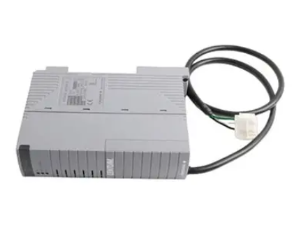
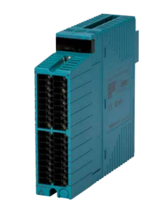
ABB 1MRK00008-KB is a specialized control module for industrial control and power system fields, belonging to ABB's relay protection and automation product series. Its core function is to achieve precise monitoring of equipment operation status, logical control, and fault linkage processing. Its model code complies with ABB's power automation product specifications, and "1MRK" is the core code prefix for relay protection and control products, representing that the module is suitable for key links in power systems or industrial control; 00008-KB "is the specific model identification, covering hardware versions, functional configurations, and other details, which can be adapted to control requirements in different scenarios.
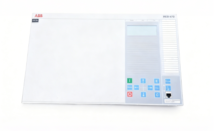
ABB 1MRK00008-KB Control Module
Product Overview
ABB 1MRK00008-KB is a specialized control module for industrial control and power system fields, belonging to ABB's relay protection and automation product series. Its core function is to achieve precise monitoring of equipment operation status, logical control, and fault linkage processing. Its model code complies with ABB's power automation product specifications, and "1MRK" is the core code prefix for relay protection and control products, representing that the module is suitable for key links in power systems or industrial control; 00008-KB "is the specific model identification, covering hardware versions, functional configurations, and other details, which can be adapted to control requirements in different scenarios.
This module adopts a compact design, integrating functions such as signal acquisition, logical operation, and instruction output. It can work in conjunction with various ABB protection devices and PLC systems, and is connected to the automation network through standardized communication interfaces. It provides a stable and reliable core control unit for power distribution network and industrial equipment control, and is widely used in substations, industrial plant distribution systems, and large-scale equipment control circuits.
Specification parameters
Electrical characteristics
Working voltage: DC 220V/110V (allowable fluctuation range ± 15%); Power consumption: normal operation ≤ 5W, maximum load ≤ 10W; input signal type: passive contact signal (DI), 4-20mA analog signal (AI)
Interface configuration
Digital input (DI): 8 channels (compatible with DC 24V passive contacts); Digital output (DO): 4 channels (relay output, capacity AC 250V/5A, DC 30V/5A); Analog input (AI): 2 channels (4-20mA, accuracy ± 0.5%); Communication interface: 1 RS485 (supporting Modbus RTU protocol)
Performance parameters
Logical operation response time: ≤ 100ms; analog acquisition update cycle: ≤ 200ms; relay output action time: ≤ 50ms; fault record capacity: can store 100 historical events (including timestamps, accuracy ± 1s)
Environment and Structure
Working temperature: -40 ℃~+70 ℃ (wide temperature design, suitable for harsh environments); Storage temperature: -40 ℃~+85 ℃; Protection level: IP40 (module body), IP20 (terminal block); Installation method: 35mm DIN rail installation (thickness 18mm, saving installation space)
Performance characteristics
Wide temperature and high reliability design: using industrial grade wide temperature components, the working temperature covers -40 ℃~+70 ℃, and can operate stably in harsh environments such as outdoor distribution cabinets and high-temperature industrial workshops in cold regions; At the hardware level, it integrates overvoltage protection (DC 300V transient suppression) and overcurrent protection (output circuit 10A fuse protection) to reduce the risk of equipment damage under extreme working conditions.
Flexible signal processing capability: supports 8 digital inputs and 2 analog inputs, and can simultaneously collect device status contact signals (such as circuit breaker opening and closing positions, alarm contacts) and analog parameters (such as current, voltage, temperature); Four relay outputs can directly drive small actuators (such as contactors and indicator lights) without the need for additional intermediate relays, simplifying control circuit design.
Convenient communication and integration: equipped with RS485 communication interface and native support for Modbus RTU protocol, it can easily connect to higher-level monitoring systems (such as SCADA, PLC) to achieve control command issuance, operation data uploading, and remote parameter configuration; The module address can be set through the dip switch (1-247 can be set), without software debugging, and the on-site deployment efficiency is high.
Practical fault recording and diagnosis function: Automatically record fault events during equipment operation (such as input signal abnormalities, output circuit overloads, communication interruptions), with each record containing an accurate timestamp, making it easy for operation and maintenance personnel to trace the cause of the fault; Built in self checking function, regularly checks the status of power, communication, and output circuits, and triggers alarms through DO output in case of abnormalities, improving the convenience of system operation and maintenance.
Working principle
The ABB 1MRK00008-KB control module has the core workflow of "signal acquisition logic operation instruction output status feedback", and the specific mechanism is as follows:
Signal acquisition stage: Receive passive contact signals from external devices (such as sensor and switch status signals) through DI interfaces, and convert them into digital signals through optoelectronic isolation circuits; Collect 4-20mA analog signals (such as current transmitters and temperature sensors) through AI interfaces, and convert them into digital signals through high-precision ADCs to ensure signal isolation and acquisition accuracy.
Logical operation stage: Based on internal preset control logic (such as "DO1 output triggered when DI1 is closed and AI1>16mA" and "DO2 alarm triggered when DI2 is disconnected for more than 5 seconds"), real-time operation is performed on the collected digital and analog signals; The logical rules can be remotely configured through the Modbus protocol of the higher-level monitoring system, or modified through local dedicated debugging software, without the need to replace hardware to adapt to different control scenarios.
Instruction output stage: When the logical operation meets the triggering conditions, the module drives the corresponding relay output (DO) to send control instructions to the executing mechanism (such as closing the contactor, lighting the alarm light); The output circuit is equipped with a surge suppression circuit (RC absorption circuit) to reduce electromagnetic interference during relay operation and protect the output contacts and actuator.
State feedback and recording stage: Real time monitoring of its own operating status (power supply voltage, communication link, output circuit load), uploading operating data (such as input signal status, analog acquisition values, output status) to the higher-level system through RS485; If an abnormality is detected (such as power supply voltage below 85% rated value, output circuit overload), immediately trigger a local alarm (such as DO3 output alarm signal), and record the fault event to local storage, providing a basis for subsequent operation and maintenance.
- User name Member Level Quantity Specification Purchase Date
- Satisfaction :
-


