Welcome to the Industrial Automation website!

NameDescriptionContent
HONG  KANG
E-mail  
Password  
  
Forgot password?
  Register
当前位置:
  • ABB 500BIM01 1MRB150024R0002 Digital Input Module
    ❤ Add to collection
  • ABB 500BIM01 1MRB150024R0002 Digital Input Module

    110V-380V
    5W-130W
    1A-30A
    1 year
    30
    United States, France, Japan, Viet Nam, Australia, Russia, Germany, Italy, Arabia

    Model identification

    500BIM01 1MRB150024R0002

    1MRB150024R0002 is the official ABB order number, and 500BIM01 is the module functional model

    Module Type

    Digital Input (DI) Module

    Only used for collecting external digital signals, without output control function

    Suitable for PLC systems

    ABB AC500 series PLC

    It needs to be used in conjunction with AC500 series CPU modules and baseboards, and supports bus expansion

    Power demand

    Logic power supply: DC 24V ± 10%; Signal power supply: shared with logic power supply

    Industrial grade wide voltage design, adaptable to on-site power fluctuations

    power consumption

    Typical value ≤ 3W

    Low power design to reduce overall system energy consumption


    • ¥8894.00
      ¥9137.00
      ¥8894.00
      ¥8894.00
    • Satisfaction:

      Sales: 0

      Review: 0

    Weight:4.480KG
    • Quantity:
    • (Inventory: 99999)
Description

Model identification

500BIM01 1MRB150024R0002

1MRB150024R0002 is the official ABB order number, and 500BIM01 is the module functional model

Module Type

Digital Input (DI) Module

Only used for collecting external digital signals, without output control function

Suitable for PLC systems

ABB AC500 series PLC

It needs to be used in conjunction with AC500 series CPU modules and baseboards, and supports bus expansion

Power demand

Logic power supply: DC 24V ± 10%; Signal power supply: shared with logic power supply

Industrial grade wide voltage design, adaptable to on-site power fluctuations

power consumption

Typical value ≤ 3W

Low power design to reduce overall system energy consumption


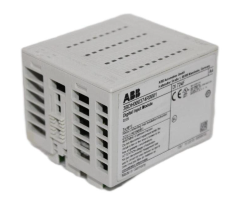
ABB 500BIM01 1MRB150024R0002 Digital Input Module

Basic information of module core

Model identification

500BIM01 1MRB150024R0002

1MRB150024R0002 is the official ABB order number, and 500BIM01 is the module functional model

Module Type

Digital Input (DI) Module

Only used for collecting external digital signals, without output control function

Suitable for PLC systems

ABB AC500 series PLC

It needs to be used in conjunction with AC500 series CPU modules and baseboards, and supports bus expansion

Power demand

Logic power supply: DC 24V ± 10%; Signal power supply: shared with logic power supply

Industrial grade wide voltage design, adaptable to on-site power fluctuations

power consumption

Typical value ≤ 3W

Low power design to reduce overall system energy consumption


Key performance characteristics

1. Signal acquisition capability

This module has 16 independent digital input channels, each of which can be independently configured with signal types. It supports sensor signal input of PNP and NPN polarities, without the need for hardware jumper switching. Parameter settings can be directly made through programming software, greatly improving the flexibility of on-site installation and debugging. The input signal voltage range is DC 15V-30V, suitable for common 24V DC sensors in industrial fields. The typical input current value is 2.5mA (at DC 24V), which can effectively avoid module damage caused by excessive signal current.

2. Response speed and filtering characteristics

The module adopts a high-speed signal processing chip, and the response time of each input channel can be flexibly configured through software within the range of 1ms-100ms to meet the real-time signal requirements in different scenarios. For high-speed motion control scenarios, a short response time can be set, and for complex interference environments, the response time can be extended to enhance the filtering effect. Built in hardware RC filtering circuit and software digital filtering algorithm can effectively suppress electromagnetic interference (EMI) and radio frequency interference (RFI) on site, ensuring the accuracy of signal acquisition in strong interference environments such as motor start stop and frequency converter operation.

3. Anti interference and reliability design

The module follows industrial grade EMC (electromagnetic compatibility) standards and has passed EN 61000-6-2 (anti-interference) and EN 61000-6-4 (emission) certifications. It has ± 2kV electrostatic discharge (ESD) protection capability and ± 1kV electrical fast transient burst (EFT) protection capability, and can be directly applied to harsh electromagnetic environments in industrial sites. Adopting isolation design, photoelectric isolation is achieved between channels as well as between channels and power supply and bus. The isolation voltage can reach 500V AC (rms), effectively preventing external signal interference from entering the PLC system bus and ensuring the stable operation of the entire control system.

4. Diagnostic and maintenance functions

The module has complete self diagnosis and fault alarm functions, and provides real-time feedback on the working status of the module through LED indicator lights. The power indicator light (PWR) displays the power supply status of the module, and the bus indicator light (BUS) displays the communication status with the CPU. Each input channel is equipped with status indicator lights (DI1-DI16), which intuitively display the signal status of the corresponding channel. When there is an abnormal situation such as power failure, bus communication interruption, channel overcurrent, etc., the module will upload the fault information to the CPU through the bus, which facilitates the operation and maintenance personnel to quickly locate the fault point through programming software and reduce maintenance costs.


Installation and configuration points

1. Mechanical installation

The module adopts a standard DIN rail installation method, with dimensions of 120mm (height) × 100mm (width) × 22.5mm (depth), and can be compactly arranged and installed with other I/O modules, CPU modules, and power modules in the AC500 series, saving control cabinet space. During installation, it is necessary to ensure that the bus interface at the bottom of the module is fully engaged with the AC500 motherboard to avoid communication failures caused by poor contact. At the same time, at least 5mm of heat dissipation space should be reserved around the module to prevent high temperature environments from affecting module performance.

2. Wiring specifications

The module adopts spring type terminal blocks, supporting wire connections of 0.5mm ² -2.5mm ². Wiring does not require tools, and wire insertion and removal can be completed by pressing the terminal, improving wiring efficiency. When wiring, it is necessary to distinguish between power terminals (L+, M) and signal terminals (DI1-DI16, COM). The common terminal (COM) of all input signals must be reliably connected to the negative terminal (M) of the module power supply to ensure the integrity of the signal circuit. For long-distance signal transmission (over 10m), it is recommended to use shielded wires and ground the shielding layer at one end to further enhance anti-interference capability.

3. Software configuration

The module needs to be configured through ABB AC500 series dedicated programming software CODESYS or ABB Automation Builder. In the software, you need to first create a project and select the corresponding CPU model, then add the "500BIM01" module and match the order number "1MRB150024R0002" to complete the bus mapping between the module and the CPU. Subsequently, the response time, signal polarity, and other parameters of each channel can be configured according to on-site requirements, and the real-time monitoring of module operation status and channel signal values can be achieved through the software's online diagnostic function.


Application scenarios and precautions

1. Typical application scenarios

-Manufacturing production line: Collecting signals from conveyor limit switches, photoelectric sensors, buttons, etc. to achieve process linkage control.

-Energy industry: used for monitoring the switch status of substations and photovoltaic power stations, such as collecting the on/off status of circuit breakers and isolating switches.

-Chemical and Metallurgical: Collect signals such as temperature switches, pressure switches, and liquid level switches around the explosion-proof area to ensure production safety.

-Intelligent building: Monitor signals such as access control switches, fire alarm buttons, and fan start stop status to achieve building automation control.

2. Precautions for use

1. The module needs to be used under specified environmental conditions: working temperature is -25 ℃~+60 ℃, relative humidity is 5%~95% (no condensation), avoid installation in high temperature, high humidity, dusty or corrosive gas environments.

2. It is strictly prohibited to plug or unplug wiring terminals or bus interfaces while the module is live, in order to avoid arc damage to the internal circuit of the module.

3. The input signal voltage should not exceed DC 30V, otherwise it will cause permanent damage to the channel. During on-site debugging, it is necessary to first confirm that the sensor output voltage meets the requirements.

4. Maintenance of module faults should be carried out by professional technicians. It is prohibited to disassemble the module casing without authorization to avoid damaging the isolation performance or causing safety hazards.
  • User name Member Level Quantity Specification Purchase Date
  • Satisfaction :
No evaluation information
  • TRICON ®/ Installation and maintenance of E/E2/E3 transmitters
  • TRLC0NEX Tricon fault-tolerant controller
  • WAGO 221 series LEVER-NUTS ® Compact splicing connector
  • WAGO-I/O-SYSTEM 750 Programmable Fieldbus Controller ETHERNET 
  • WAGO Rail-Mount Terminal Blocks with Screw and Stud Connection
  • WAGO series molded case circuit breaker (MCCB)
  • WAGO Rail-Mount Terminal Blocks
  • WAGO I/O System 750/753 Series Distributed Automation System
  • HIMA X-CPU 01 processor module
  • Westinghouse iGen5000 Digital Inverter Generator
  • Westinghouse WGen7500DF Dual Fuel Portable Generator
  • Westinghouse WPX2700H/WPX3100H High Pressure Cleaning Machine
  • Westinghouse WH7500V portable generator
  • Westinghouse WGen9500c portable generator
  • Westinghouse DS/DSL series low-voltage power circuit breakers
  • Westinghouse ePX3500 Electric High Voltage Cleaning Machine
  • Westinghouse ST Switch Intelligent Automatic Portable Transfer Switch
  • Westinghouse 2400i digital inverter generator
  • Westinghouse iGen series digital inverter generator
  • HIMA CPU 01 Controller Module
  • Westinghouse WPX3000e/WPX3400e electric high-pressure cleaning machine
  • Westinghouse WGen2000, WGen3600, and WGen3600V portable generators
  • Westinghouse WGen5500 Generator
  • Westinghouse WGen20000 Generator
  • Westinghouse WPro8500 and WPro12000 portable generators
  • Westinghouse iGen4500DFc Dual Fuel Digital Variable Frequency Generator
  • Watlow Series L Temperature Limiting Controller
  • Watlow Series F4P Temperature/Process Controller
  • Watlow EZ-ZONE ® RME (Expansion) Module
  • Watlow EZ-ZONE ® RMA (Access) module
  • Watlow PM PLUS ™ 6 Series PID Integrated Controller
  • Watlow Immersion Heater
  • Watlow F4T Controller Installation and Failure
  • Watlow DIN-A-MITE ® Style C Solid State Power Controller
  • Watlow plug-in heater
  • Watlow Series 942 Controller
  • Watlow Series 988 Controller
  • Watlow Series 146 Temperature Regulator
  • Watlow PM LEGACY ™ Limit controller
  • How to install Johnson AE55/NIE55?
  • Watlow Series 96 Temperature Controller
  • Watlow PM PLUS ™ PID/Integrated Limit Controller
  • Watlow Ceramic Fiber Heater
  • Watlow Power Series microprocessor based SCR power controller
  • Watlow thermocouple products
  • Watlow Series 965 Controller
  • Watlow PM3 LEGACY ™ PID controller
  • Watlow Series 93 Controller
  • Watlow EZ-ZONE ® PM PID controller
  • Watlow CLS200 series controller
  • YAMAHA RCX40 4-axis robot controller
  • YASKAWA Z1000 series HVAC dedicated frequency converter
  • YASKAWA HV600&Z1000U series HVAC dedicated frequency converter
  • YASKAWA Power Regenerative Unit R1000 Series
  • YASKAWA AC Drive P1000 Industrial Fan and Pump Special Frequency Converter
  • YASKAWA FP605 series industrial fan pump dedicated driver
  • YASKAWA GA500 series AC micro driver
  • YASKAWA AC Drive G7 Series (Model CIMR-G7U)
  • YASKAWA U1000 series 24V power supply options (PS-U10L/PS-U10H)
  • YASKAWA GA800 industrial AC frequency converter Key issues
  • How to select YASKAWA GA800 industrial AC frequency converter?
  • YASKAWA AC Drive V1000 Compact Vector Control Drive
  • YASKAWA Control Pack CP-317M System Controller
  • YASKAWA VARISPEED-626M/656MR5 series vector control frequency converter
  • YASKAWA AC Servo Drive HR Series (CACR-HR) Multi functional/Positioning Control
  • YASKAWA MP2000 series machine controller communication module
  • Yokogawa AQ1100 series OLTS multi field tester
  • YOKOGAWA AQ7280 Optical Time Domain Reflectometer
  • YOKOGAWA AQ2200 Series Multi Application Testing System
  • YOKOGAWA AQ6150B/AQ6151B Optical Wavelength Meter
  • YOKOGAWA AQ6360 Optical Spectrum Analyzer
  • Yokogawa AQ6375E Spectral Analyzer Remote Control
  • Yokogawa DL350 Scope Order Communication Interface
  • Yokogawa 701944/701945 100:1 High Voltage Probe
  • Yokogawa CA700 pressure calibrator
  • Yokogawa DLM5000HD series high-definition oscilloscope
  • Yokogawa AQ1210 Series OTDR Multi Field Tester
  • Yokogawa AQ1000 OTDR Optical Time Domain Reflectometer
  • YOKOGAWA WT1801R series precision power analyzer communication interface
  • YOKOGAWA DLM3034HD/DLM3054HD High Definition Oscilloscope
  • YOKOGAWA AQ23011A/AQ23012A Modular Framework Equipment
  • YOKOGAWA DLM3054HD Mixed Signal Oscilloscope
  • YOKOGAWA CW500 Power Quality Analyzer
  • How to troubleshoot the YOKOGAWA CA500/CA550 multifunctional process calibrator?
  • How to maintain YOKOGAWA AQ7420 High Resolution Reflectometer?
  • YOKOGAWA FG410/FG420 arbitrary waveform editor
  • How to check the packaging and accessories of Yokogawa Model 701905 conversion cable?
  • YOKOGAWA MY600 Digital Insulation Resistance Tester
  • YOKOGAWA AQ7290 Series Optical Time Domain Reflectometer OTDR
  • How to ensure the safety and maintenance of YOKOGAWA LS3300 AC power calibrator?
  • Yokogawa AQ6377E Optical Spectrum Analyzer Remote Control
  • Yokogawa AQ6361 Optical Spectrum Analyzer
  • Yokogawa IS8000 Integrated Software ECU Monitoring and Synchronization Function
  • Yokogawa ROTAMASS TI Coriolis Mass Flow Meter
  • Yokogawa ROTOMETER RAMC Metal Variable Area Flow Meter
  • Yokogawa SL1000 high-speed data acquisition unit input module
  • How to install and wire the Yokogawa FLXA402T turbidity and chlorine liquid analyzer?
  • Yokogawa WTB10-DO Series Dissolved Oxygen Measurement System Terminal Box
  • Yokogawa Model 702928 PBD0200 Differential Probe
  • YOKOGAWA ADMAG TI Series AXW Electromagnetic Flow Meter (25-450mm) Installation and Operation
  • How to troubleshoot YOKOGAWA ADMAG TI series AXW electromagnetic flowmeter (25-1800mm)?
  • How to install YOKOGAWA DO30G dissolved oxygen sensor?
  • YOKOGAWA SC4AJ Conductivity Sensor Manual
  • YOKOGAWA SC210G Conductivity Detector
  • How to install and wire Yokogawa PH4/OR4 series pH and ORP sensor (IM12B10B00-01EN)?
  • How to troubleshoot Yokogawa OR8EFG KCl filled ORP sensor (IM12C07J01-01E)?
  • YOKOGAWA FU24 pH/ORP Composite Sensor with Pressure Compensation (IM 12B06J03-03EN-P)
  • Yokogawa SC200 Intelligent Two Wire Conductivity Transmitter System (IM12D08B01-01E)
  • YOKOGAWA CENTUM VP Integrated Production Control System (TI33J01A10-01EN)
  • ABB AO2000-LS25 Laser Analysts User Manual
  • YOKOGAWA FA-M3 positioning module (with analog voltage output)
  • YOKOGAWA FA-M3 Series Basic Modules
  • YOKOGAWA EJA110E Diff erential Pressure Transmitter
  • Zygo 3D Optical Profiler
  • How to unpack and install the Zygo Mark II 4-inch interferometer system?
  • Zygo NewView 9000 3D Optical Profilometer Technology Advantages
  • Zygo NewView 9000 3D Optical Profilometer Technology
  • Zygo Profilometer Standard Operating Procedure
  • Zygo’s Guide to Typical Interferometer Setups
  • ZYGO Laser Interferometer Accessory Guide OMP-0463AM
  • ZYGO MetroPro 9.0 Reference Guide (OMP-0347M)
  • Zygo Device Standard Operating Procedure (SOP)
  • Zygo Verify Laser Interferometer Product Highlights
  • Zygo MicroLUPI Micro Hole Diameter Laser Unequal Path Interferometer
  • ZYGO ZMI-1000 Displacement Measuring Interferometer System
  • Zygo’s ZMI 2000 System Displacement Measuring Interferometer Systems
  • ABB IGCT Technology: A Revolutionary Breakthrough in High Voltage Inverters
  • Siemens 6AG1204-2BB10-4AA3 Ethernet Switch