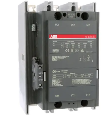
AF400-30 is an AC contactor developed by ABB for industrial high-power load control requirements. In the model, "AF" represents the ABB standard AC contactor series, "400" represents the rated working current reference value, and "30" represents a contact configuration with 3 sets of normally open main contacts and 0 sets of normally closed main contacts. The contactor adopts an integrated structure design of "electromagnetic operation contact execution arc extinguishing protection". Its core function is to achieve rapid on-off of the main circuit under the action of control signals, thereby controlling the start stop operation of high-power motors, transformers and other loads. It abandons the defects of traditional contactor contacts that are prone to wear and have poor arc extinguishing effects. It adopts silver alloy contact material and a closed arc extinguishing chamber design, combined with an optimized electromagnetic operating mechanism, which can stably carry ultra-high current at rated voltage, effectively extinguishing the arc generated when the contact is disconnected, and avoiding arc erosion of the contact. At the same time, its standardized installation dimensions and terminal design are compatible with ABB's full range of motor protection components and control modules, providing support for the flexible construction and integration of high-power load control systems.
ABB AF400-30 contactor
Product Overview
AF400-30 is an AC contactor developed by ABB for industrial high-power load control requirements. In the model, "AF" represents the ABB standard AC contactor series, "400" represents the rated working current reference value, and "30" represents a contact configuration with 3 sets of normally open main contacts and 0 sets of normally closed main contacts. The contactor adopts an integrated structure design of "electromagnetic operation contact execution arc extinguishing protection". Its core function is to achieve rapid on-off of the main circuit under the action of control signals, thereby controlling the start stop operation of high-power motors, transformers and other loads. It abandons the defects of traditional contactor contacts that are prone to wear and have poor arc extinguishing effects. It adopts silver alloy contact material and a closed arc extinguishing chamber design, combined with an optimized electromagnetic operating mechanism, which can stably carry ultra-high current at rated voltage, effectively extinguishing the arc generated when the contact is disconnected, and avoiding arc erosion of the contact. At the same time, its standardized installation dimensions and terminal design are compatible with ABB's full range of motor protection components and control modules, providing support for the flexible construction and integration of high-power load control systems.
Core functional features
1. Ultra high current carrying capacity, suitable for high-power load requirements
The main contact of the contactor is made of highly conductive silver cadmium alloy material. The contact area of the contact has been optimized and designed with a multi-point contact structure, greatly improving the current carrying capacity. The rated working current can reach 400A (under the AC-3 usage category), which can directly adapt to the starting control requirements of three-phase asynchronous motors with a power of less than 200kW. The main circuit adopts copper bar type terminal blocks, supporting the connection of copper wires with a maximum cross-sectional area of 50mm ², with a contact resistance of ≤ 100 μ Ω. When operating at rated current, the contact temperature rise is ≤ 60K, far below the national standard limit, effectively reducing power loss and avoiding contact fusion failure caused by overheating. At the same time, the contactor has excellent short-time withstand current performance, with a rated short-time withstand current (Icw) of 10kA/1s, which can withstand 6-8 times the rated current surge during motor start-up, ensuring the safety of the main circuit.
2. Efficient arc extinguishing system to ensure safe and reliable disconnection
In response to the strong arc generated during the breaking of high-power loads, the contactor is equipped with a closed longitudinal seam arc extinguishing chamber. The arc extinguishing chamber is made of arc resistant ceramic material and is equipped with multiple metal arc extinguishing grids inside, which can quickly divide and cool the arc, achieving rapid extinguishing of the arc. Under the AC-3 usage category, the rated breaking current of the contactor can reach 1000A, with a breaking time of ≤ 10ms, which can effectively avoid problems such as contact erosion and insulation breakdown caused by continuous arc combustion between contacts. At the same time, the arc extinguishing chamber adopts a fully enclosed structure design, which can prevent arc leakage, avoid high-temperature burns or electromagnetic interference to surrounding electrical components, and enhance the safety protection level of the entire control system.
3. Optimize the electromagnetic mechanism to achieve low-power stable operation
The contactor adopts an energy-saving electromagnetic operating mechanism. By optimizing the structure of the electromagnetic iron core and coil parameters, the coil power consumption is significantly reduced while ensuring the operating torque. Under rated control voltage, the coil suction power consumption is ≤ 800VA, and the holding power consumption is ≤ 80VA, which saves more than 40% energy compared to traditional contactors, effectively reducing the heat generation inside the control cabinet and lowering the cost of the cooling system. The electromagnetic mechanism is equipped with a dual coil design (attraction coil+holding coil), which generates strong magnetic force through high current during attraction to quickly close the contacts. After closure, it automatically switches to the holding coil power supply, ensuring the reliability of contact closure and reducing long-term energy consumption. At the same time, the surface of the iron core is treated with a special coating, combined with dust-proof sealing design, which can effectively reduce mechanical wear and improve the stability of the mechanism action. The mechanical life of the electromagnetic mechanism can reach more than 10 million times.
4. Modular contact configuration enhances system adaptability flexibility
The contactor adopts a modular contact design, with a main contact configuration of 3 sets of normally open (30 structure). Auxiliary contact modules can be flexibly added according to control requirements, supporting up to 4 sets of auxiliary contacts (2 open 2 closed or 3 open 1 closed combination, etc.). The rated current of the auxiliary contacts is 10A, which can be used for signal interlocking, status feedback and other functions of the control circuit. At the same time, the contactor supports the installation of mechanical interlocking modules to achieve interlocking control between two contactors, avoiding power reversal or short circuit faults in the main circuit, especially suitable for motor forward and reverse control scenarios. Modular design enables flexible configuration of contactors according to different control requirements, without the need to replace the contactor body, greatly improving the adaptability and economy of the product.
5. Comprehensive protection functions to enhance operational safety
The contactor is equipped with multiple protection mechanisms. Firstly, it is equipped with overvoltage protection function. The two ends of the coil are connected in parallel with varistors, which can absorb instantaneous overvoltage in the control circuit and avoid coil burnout; Secondly, the main contact is equipped with a wear indicator device. When the wear of the contact reaches the limit, the indicator device will send a clear signal to remind the operation and maintenance personnel to replace the contact in a timely manner; In addition, the contactor housing is made of engineering plastic with a flame retardant rating of UL94 V-0, which has good insulation performance and high temperature resistance. The insulation resistance is ≥ 100M Ω (500V DC), and the electrical strength reaches 5kV AC/1min, which can effectively prevent electrical faults such as leakage and short circuit, and ensure the safety of personnel and equipment.
6. Convenient installation and maintenance, reducing operation and maintenance costs
The contactor adopts a dual installation method of standard 35mm DIN rail installation and bolt fixation, with compact installation space. It can be tightly arranged with ABB series thermal overload relays, circuit breakers and other components in the control cabinet, saving installation space. The terminal block adopts a crimping design and is equipped with anti loosening nuts, making the wiring firm and reliable, avoiding loose wiring caused by vibration; The contact replacement adopts a modular design, which can complete the replacement of contact components without disassembling the contactor body, greatly reducing maintenance time. At the same time, the surface of the contactor is clearly labeled with wiring identification and parameter information, making it easy for installation personnel to quickly identify and operate, and reducing the rate of wiring errors.
Key technical parameters
Model
AF400-30 (3 sets of normally open main contacts, non closing main contacts)
Usage category
AC-1 (resistive load), AC-3 (motor start and operation), AC-4 (motor start and reverse braking)
Rated working current (Ie)
400A at AC-3 400V; 630A at AC-1 400V
Rated working voltage (Ue)
Main circuit: AC 220V/380V/400V/690V; Control circuit: AC 24V/110V/220V/380V
Rated breaking current (Icu)
1000A at AC-3 400V; 800A at AC-4 400V
Short time withstand current (Icw)
10kA/1s(400V AC)
Coil power consumption
Pull in power consumption ≤ 800VA; hold power consumption ≤ 80VA
Contact material
Main contact: silver cadmium alloy; Auxiliary contact: Silver nickel alloy
mechanical life
≥ 10 million times
Electrical lifespan
AC-3 usage category ≥ 1 million times; AC-1 usage category ≥ 10 million times
insulation performance
Insulation resistance ≥ 100M Ω (500V DC); Electrical strength 5kV AC/1min
Contact temperature rise
≤ 60K at rated current (refer to IEC 60947 standard)
Arc extinguishing method
Closed longitudinal seam arc extinguishing chamber+metal arc extinguishing grid
Installation method
35mm DIN rail installation, bolt fixation
working environment
Temperature: -25 ℃ -60 ℃; Humidity: 5% -95% (no condensation); Protection level: IP20
Shell material
Flame retardant engineering plastic, flame retardant grade UL94 V-0
Auxiliary contact configuration
Scalable, supporting up to 4 sets of auxiliary contacts (rated current 10A)
Typical application scenarios
The AF400-30 contactor is widely used in various high-power load control scenarios due to its ultra-high current carrying capacity, reliable arc extinguishing performance, and flexible adaptability. Typical applications include:
1. Industrial motor start control: In high-power motor control systems such as steel rolling motors in steel enterprises, reaction kettle mixing motors in chemical enterprises, and ball mill motors in building materials enterprises, contactors serve as the main executing components, receiving control signals from PLCs or controllers to achieve motor start, operation, and stop control. With a rated current of 400A and a short-time withstand current of 10kA, it can easily cope with the large current impact during motor start-up. Combined with a thermal overload relay, it achieves overload protection for the motor, ensuring safe operation of the motor.
2. Load control of fans and water pumps: In high-power fan and water pump control systems such as induced draft fans and supply fans in thermal power plants, sewage lifting pumps in sewage treatment plants, and water supply pumps in water plants, contactors are used to control the start stop and operation of loads. Its low-power electromagnetic mechanism can effectively reduce the energy consumption during long-term operation, and the modular auxiliary contacts can achieve interlocking control of the fan and water pump (such as sequential start-up of the induced draft fan and the supply fan). The arc extinguishing system ensures reliable disconnection in humid environments and avoids faults.
3. Heating equipment control in the metallurgical industry: In the heating furnace of steel enterprises and the electrolytic cell heating system of non-ferrous metal smelting, contactors are used to control the power on/off of heating elements, achieving temperature regulation during heating. The rated current of 630A under its AC-1 usage category can adapt to high-power heating loads. The high-temperature resistant shell material and reliable insulation performance can adapt to the high temperature and dusty environment in metallurgical workshops, ensuring stable operation of the heating system.
4. Switching of low-voltage distribution system: In the low-voltage distribution system of industrial plants and data centers, contactors are used for automatic switching of dual power supply circuits. When the main power supply fails, the contactors quickly disconnect the main power supply and close the backup power supply under the action of the control module, achieving undisturbed switching of the power supply. Its fast breaking speed (≤ 10ms) and reliable contact performance ensure continuous power supply to the distribution system, avoiding production interruptions or data loss caused by power outages.
5. Motor forward and reverse control: In equipment control systems such as cranes and conveyors that require forward and reverse operation, two AF400-30 contactors are used in conjunction with mechanical interlocking modules to achieve motor forward and reverse control. The interlocking module can effectively prevent the main circuit from short circuiting caused by the simultaneous closing of two contactors, and the auxiliary contacts are used for signal feedback of the control circuit, ensuring the safe and reliable switching of equipment operation direction.
Precautions for use
1. Parameter matching confirmation: Before use, it is necessary to confirm that the rated current and voltage of the contactor are completely matched with the parameters of the controlled object, especially in motor control scenarios. The appropriate usage category (AC-3 or AC-4) should be selected based on the motor power and starting mode (direct start, star delta start) to avoid contactor contact burnout or motor failure to start normally due to parameter mismatch. The voltage of the control circuit should be consistent with the rated voltage of the coil to prevent the coil from being burnt out due to overvoltage or undervoltage, which may cause the contacts to not be firmly engaged.
2. Installation environment control: The contactor should be installed in a well ventilated control cabinet without direct sunlight. The control cabinet should be equipped with a cooling fan to ensure that the temperature inside the cabinet is controlled within the range of -25 ℃ -60 ℃, to avoid high temperature causing coil aging or excessive temperature rise of contacts; The installation position should be far away from strong vibration sources and corrosive gases. If necessary, shock absorbers and dust covers should be installed to prevent poor contact of the contacts caused by vibration or corrosion of the contacts by corrosive gases.
3. Wiring operation specifications: Before wiring, the power supply of the main circuit and control circuit must be cut off, and live wiring is strictly prohibited; The main circuit wiring terminals need to be tightened with a torque wrench according to the specified torque (≥ 25N · m) to avoid increased contact resistance and heat burning caused by loose wiring; The control circuit wiring should use copper wires with a cross-sectional area of ≥ 1.5mm ² to avoid excessive voltage drop caused by thin wires; The wires of the main circuit and control circuit should be laid separately to reduce electromagnetic interference.
4. Interlocking and protection configuration: In the scenario of motor forward and reverse control or dual power switching, mechanical interlocking or electrical interlocking devices must be equipped to prevent short circuits caused by the simultaneous closure of the main contacts; Contactors must be used in conjunction with protective components such as thermal overload relays and circuit breakers to achieve overload and short circuit protection, avoiding the expansion of accidents caused by the isolated operation of contactors in the event of motor or main circuit failures; The control circuit should be equipped with fuses to protect the coil from overcurrent impact.
5. Operation status monitoring: During daily operation, it is necessary to regularly check the operation status of the contactor, including contact temperature rise (detected with an infrared thermometer, normal should be ≤ 60K), electromagnetic mechanism operation noise (there should be no abnormal noise), and contact wear indicator device status; Monitor the coil voltage and current through the control circuit to ensure that the coil is working properly; When burn marks are found on the contacts, the electromagnetic mechanism is not smoothly engaged, or the temperature rise is abnormal, it is necessary to stop the machine for maintenance in a timely manner.
6. Maintenance requirements: Regularly (recommended every six months) clean the contactor, use a dry brush to remove dust from the surface and contact area, and avoid dust accumulation that may cause a decrease in insulation performance; Check the wear of the contacts. When the wear of the contacts exceeds 1mm, the contact components should be replaced in a timely manner; Check the lubrication condition of the iron core surface of the electromagnetic mechanism. If dryness is found, apply special lubricating grease; Regularly tighten the wiring terminals to prevent loosening and oxidation.
7. Fault handling specifications: When a contact welding fault occurs in the contactor, the power should be immediately cut off, the contact components should be replaced, and the cause of overload should be investigated; If the coil burns out, it is necessary to check whether the control circuit voltage is abnormal. Before replacing the coil, it is necessary to confirm that there is no short circuit problem in the control circuit; If the contact is not firmly engaged, it is necessary to check the coil voltage and whether there is oil or impurities on the surface of the iron core. Clean and adjust the coil voltage to the rated value in a timely manner.
- User name Member Level Quantity Specification Purchase Date
- Satisfaction :
-


