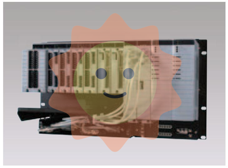
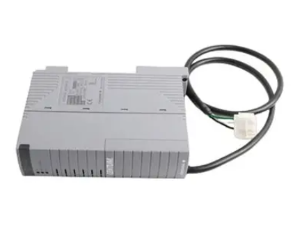
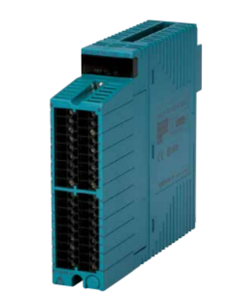
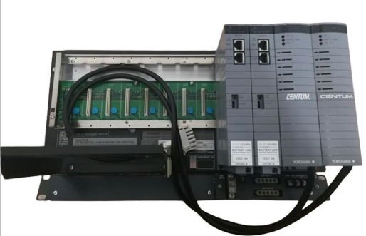
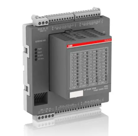
ABB M3V4-1/0-0 64122088 is a hybrid input-output module designed specifically for the M300 series compact controllers. Its main function is to achieve on-site digital signal acquisition and analog control signal output. In the control system architecture, this module achieves high-speed data exchange with the M300 controller through a dedicated bus and receives control instructions issued by the controller; On the other side, it is directly connected to on-site sensors (such as photoelectric switches, proximity switches) and actuators (such as regulating valves, solenoid valves) to complete real-time acquisition of digital signals and accurate distribution of analog output signals.
ABB M3V4-1/0-0 64122088 Input/Output Module
Module core positioning and product attributes
ABB M3V4-1/0-0 64122088 is a hybrid input-output module designed specifically for the M300 series compact controllers. Its main function is to achieve on-site digital signal acquisition and analog control signal output. In the control system architecture, this module achieves high-speed data exchange with the M300 controller through a dedicated bus and receives control instructions issued by the controller; On the other side, it is directly connected to on-site sensors (such as photoelectric switches, proximity switches) and actuators (such as regulating valves, solenoid valves) to complete real-time acquisition of digital signals and accurate distribution of analog output signals.
Compared with standalone I/O modules, this module adopts an integrated design that matches the M300 controller, with a more compact size and more convenient wiring. It can achieve seamless integration with the controller without the need for additional communication modules, effectively reducing system integration costs and space occupancy. It has optimized signal processing for complex industrial environments and has strong anti-interference ability, which can stably adapt to the needs of various small and medium-sized control scenarios.
Core functional features and technological advantages
1. Hybrid I/O design that meets the needs of multiple scenarios
The module adopts a mixed configuration mode of "digital input+analog output", in which the digital input channel can directly collect the switch status signals of on-site devices (such as device operation/stop, fault alarm, etc.), supporting multiple signal types such as dry contacts and wet contacts; The analog output channel can output standard control signals, which are used to drive actuators such as regulating valves and frequency converters, to achieve continuous adjustment of process parameters such as pressure, flow rate, and speed. This hybrid design enables the module to complete the construction of simple control circuits without the need for other I/O modules, improving the flexibility and economy of system configuration.
2. High precision signal processing to ensure data reliability
In the digital input stage, the module is equipped with a built-in photoelectric isolation circuit and signal filtering unit, which can effectively suppress the influence of on-site electromagnetic interference on the input signal and avoid signal misjudgment caused by interference; Simultaneously supporting signal stabilization function, the stabilization time (0.1ms-100ms) can be set through configuration software to adapt to the signal characteristics of different types of sensors. In the analog output stage, the module adopts a high-precision D/A conversion chip, and the linearity error of the output signal is ≤ 0.1% FS, ensuring the precise transmission of control instructions and enabling the actuator to operate stably in the target working state.
3. Fast bus communication improves system response efficiency
The module is connected to the controller through the ABB M300 series dedicated internal bus, with a communication speed of over 1Mbps and a data transmission delay of ≤ 1ms. It can achieve real-time uploading of input signals and rapid issuance of output commands. This high-speed communication capability ensures the control system's rapid response to changes in on-site working conditions, especially suitable for scenarios such as mechanical processing and assembly line control that require high response speed, effectively improving the control accuracy of the production process.
4. Comprehensive status monitoring and fault alarm functions
The module has comprehensive self state monitoring capability, which can monitor its own power supply status, bus communication status, and signal status of each channel in real time. When there is a power failure, bus interruption, channel overload or other faults, the module will immediately upload the fault information (including the fault channel and fault type) to the controller through the bus, and trigger the module's own fault indicator light, making it easy for operation and maintenance personnel to quickly locate the problem. In addition, the digital input channel supports wire breakage detection function, which can timely detect faults such as loose or broken sensor cables, reducing the risk of system operation.
5. Compact structure and convenient installation, reducing integration costs
The module adopts a standard DIN rail installation method, with a compact size (only 1-2 module positions wide), and can be tightly arranged and installed with M300 controllers and other expansion modules, greatly saving space inside the control cabinet. The wiring adopts a spring type terminal design, which can firmly connect the cables without the use of tools, not only improving installation efficiency, but also effectively preventing loose wiring caused by vibration. At the same time, the module supports hot swapping function (subject to the permission of the controller), which can complete module replacement without interrupting system operation, reducing maintenance downtime losses.
Key technical parameters
Digital input
number of channels
4 routes
signal type
PNP/NPN compatible, supports dry contacts (passive) and wet contacts (active)
Input voltage range
24V DC(±15%)
input current
≤ 10mA per channel
response time
0.1ms-100ms (can be set through software)
Analog output
number of channels
1 Road
signal type
4-20mA DC (default), can be configured to 0-20mA DC through software
output accuracy
± 0.1% FS (at 25 ℃ ambient temperature)
Output load
≤ 500 Ω (in 4-20mA mode)
temperature coefficient
≤50ppm/℃
Communication characteristics
communication interface
M300 series dedicated internal bus
communication rate
≥1Mbps
communication delay
≤1ms
working environment
Operating Temperature
-20 ℃~60 ℃ (normal operation); -40 ℃~85 ℃ (storage)
relative humidity
5%~95% (no condensation)
Protection level
IP20 (module body)
Anti-interference performance
Compliant with IEC 61000-4-2/3/4/6 standards
Power parameters
working power supply
24V DC (± 15%), powered by M300 controller or dedicated power module
power consumption
≤ 3W during normal operation
Core points of installation and operation and maintenance
1. Installation specifications and requirements
-The module needs to be installed in a control cabinet that meets the protection level of IP54 or above, to avoid direct contact of dust and water vapor with the module; The installation location should be far away from high-power heating equipment (such as contactors and transformers), ensuring good ventilation around and an ambient temperature not exceeding 60 ℃. The installation distance from strong electromagnetic interference equipment (such as frequency converters) should not be less than 0.5 meters. If this cannot be met, metal partitions should be used for shielding.
-The module is installed using DIN rails, and it is necessary to ensure a minimum gap of 5mm between adjacent modules during installation to facilitate heat dissipation; When fixing, it is necessary to clamp the guide rail tightly to prevent module displacement caused by equipment vibration. When connecting with the M300 controller, a dedicated bus cable should be used, and the cable length should be controlled within 5 meters to avoid communication signal attenuation.
-When wiring, it is necessary to strictly follow the terminal identification. The connection between the digital input channel and the sensor should distinguish between positive and negative poles (active signals) to avoid module damage caused by reverse connection; The connection between the analog output channel and the actuator should ensure that the circuit is unobstructed to avoid short circuits. It is also recommended to use shielded cables, with the shielding layer grounded at one end to reduce interference.
-Before powering on the module, it is necessary to check whether the wiring is correct and whether the terminals are fastened. After confirming that there are no errors, power can be supplied through the controller or dedicated power module to avoid faults caused by abnormal power supply voltage or wiring errors.
2. Daily operation and troubleshooting
-During daily inspections, it is necessary to focus on observing the operation indicator lights (power lights, communication lights, channel status lights) of the modules to ensure that the power lights are always on, the communication lights are flashing normally, and the channel status lights are consistent with the on-site equipment status; If there is an abnormal indicator light, it is necessary to promptly investigate the corresponding cause of the malfunction.
-Regularly monitor the module online through ABB M300 series dedicated configuration software (such as Control Builder Plus) to check whether the input/output data of each channel is normal. If frequent fluctuations in digital input signals are found, the anti shake time can be adjusted through software; If the accuracy deviation of analog output is large, software calibration can be performed.
-When a communication failure occurs in the module, it is necessary to check whether the bus cable is loose and whether the bus interface is damaged. If necessary, replace the bus cable or re plug the interface; If it is a channel failure, the replacement method can be used to investigate and switch the load of the suspected faulty channel to the backup channel to confirm whether it is a module hardware problem. If it is a hardware failure, the module should be replaced in a timely manner.
-After long-term operation of the module, it is necessary to regularly clean the dust inside the control cabinet and on the surface of the module. When cleaning, the power should be cut off first, and a dry brush or compressed air should be used for cleaning to avoid moisture entering the module and causing short circuits; At the same time, check the fastening of the wiring terminals to prevent loose connections caused by vibration.
- User name Member Level Quantity Specification Purchase Date
- Satisfaction :
-


