
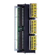
FORCE PMC234 is a high-performance industrial automation control module in the PMC series under the FORCE brand. It has the core attributes of a host bus adapter and a communication module, and is a key core component in industrial automation control systems. This module adopts a highly integrated design, with a compact structure that is easy to install and integrate with the system. By receiving external commands or sensor signals and processing them accurately, it outputs digital control signals to drive external devices or actuators, achieving precise control over the operating status and production process of industrial equipment. Its core functions include device control, data acquisition and monitoring, process parameter adjustment, etc., which can effectively improve production efficiency, reduce operation and maintenance costs, and ensure product quality stability. It is widely adapted to the application needs of multiple fields such as industrial automation and energy management.
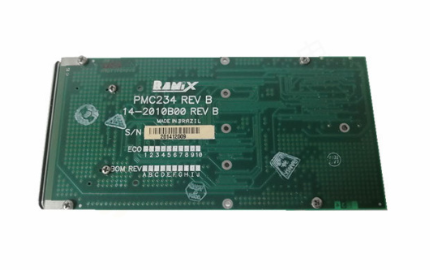
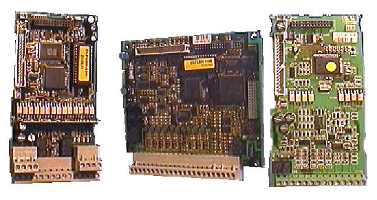
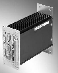
FORCE PMC234 control module
Product Overview
FORCE PMC234 is a high-performance industrial automation control module in the PMC series under the FORCE brand. It has the core attributes of a host bus adapter and a communication module, and is a key core component in industrial automation control systems. This module adopts a highly integrated design, with a compact structure that is easy to install and integrate with the system. By receiving external commands or sensor signals and processing them accurately, it outputs digital control signals to drive external devices or actuators, achieving precise control over the operating status and production process of industrial equipment. Its core functions include device control, data acquisition and monitoring, process parameter adjustment, etc., which can effectively improve production efficiency, reduce operation and maintenance costs, and ensure product quality stability. It is widely adapted to the application needs of multiple fields such as industrial automation and energy management.
Specification parameters
2.1 Core electrical parameters
-Working voltage range: 2.2V~5.5V, suitable for various industrial power supply scenarios
-Working frequency: In crystal mode and internal high RC oscillator (lHRC) mode, the frequency dynamically adjusts with voltage: up to 8MHz at 4V, up to 4MHz at ≥ 3V, up to 2MHz at ≥ 2.5V, and up to 1MHz at ≥ 2.2V
-Power consumption parameters: The operating state (1MIPs, VDD=5.0V) consumes approximately 1.7mA, while the working state (VDD=3.3V, ILRC=12KHz) consumes approximately 15 μ A; Low power mode (VDD=5.0V) consumes approximately 1 μ A, while deep low power mode (VDD=3.3V) consumes as little as 0.5 μ A
-Working temperature range: -40 ℃~85 ℃ for enhanced series, -20 ℃~70 ℃ for universal series
2.2 Hardware configuration parameters
-Core processor: Enhanced FPPATM 8-bit RISC CPU array, supporting dual processing unit FPPA mode or single processing unit traditional mode
-Storage capacity: Dual FPP units equipped with 4K x 16 bit OTP program memory and 208 bytes of data RAM
-Interface Protocol: Supports multiple high-speed interface protocols such as SATA, SAS, PCIe, etc., and can seamlessly integrate with various storage devices and upper level systems
-Expansion interface: 26 IO pins, with 10mA driver/receiver capability, supporting wake-up function configuration; 2 external interrupt pins
-Analog signal processing: up to 11 channels with 12 bit resolution ADC, 1 channel internal bandgap reference voltage (1.20V)
-Timing and control module: 1 hardware 16 bit timer, 1 hardware 8-bit timer with PWM generator; 1 hardware comparator
-Display driver: Supports software configurable LCD driver IO, optional VDD/2 LCD bias voltage, maximum support for 4 × 21 point LCD display
2.3 Environmental and mechanical parameters
-Anti interference capability: It is necessary to avoid scenarios that require AC RC buck power supply, high power ripple, or high EFT (electrical fast transient)
-Voltage monitoring: Built in 8-level LVR (low voltage reset) function, reset voltage optional 4.1 V、3.6V、3.1V、2.8V、2.5V、2.2V、2.2V、1.8V
Performance characteristics
3.1 Efficient processing performance
Equipped with a high-performance RISC CPU array, it has a built-in set of 100 powerful instructions, with most instructions having a execution cycle of only 1T, and has fast data processing and logical computing capabilities; Supports programmable stack pointers, provides adjustable stack levels, supports direct and indirect addressing modes, and all data storage can be used as index points to achieve efficient instruction execution and data access. By adopting high-speed serial bus technology, high-speed data transmission is achieved, significantly improving data read and write efficiency and ensuring real-time response of control instructions.
3.2 Flexible adaptation capability
Supports multiple interface protocols and clock source selection (internal high RC oscillator, internal low RC oscillator, external crystal oscillator), and can flexibly adapt to different device connection and operation requirements. Rich IO pins and interrupt resources, supporting multi-channel analog signal acquisition and LCD display driver, can meet the needs of multi device collaborative control and status visualization in complex industrial scenarios.
3.3 Reliable and Stable Operation
By using high-quality components and strict production processes, combined with protection mechanisms such as low voltage reset and hardware comparator, the module ensures long-term stable operation under complex working conditions such as wide temperature and low power consumption. Equipped with intelligent diagnostic functions and a simple operating interface, it facilitates users to quickly troubleshoot and perform daily maintenance, reducing the difficulty and cost of operation and maintenance.
3.4 Energy saving and Environmental Protection Characteristics
Adopting a low-power design scheme and adaptive adjustment through multiple power consumption modes, energy consumption is minimized while ensuring control performance, which meets the needs of industrial energy conservation and environmental protection development. Supports fast wake-up function, which can quickly switch between low-power standby and efficient operation, balancing energy saving and real-time response requirements.
Working principle
The FORCE PMC234 control module follows the core workflow of "signal acquisition data processing instruction output feedback regulation", relying on the internally integrated CPU array, signal conditioning circuit, and control algorithm to achieve precise control of the controlled object. The specific process is as follows:
4.1 Signal acquisition stage
The module receives external signals through input interfaces, including analog signals such as temperature, pressure, and position collected by sensors, digital signals such as switch status and pulses, and communication data from the upper system transmitted through protocols such as SATA and PCIe. After being processed by internal conditioning circuits (filtering, amplification, analog-to-digital conversion), the input signal is converted into a digital signal recognizable by the CPU and sent to the data storage for temporary storage.
4.2 Data Processing Stage
The core CPU array analyzes, calculates, and makes logical judgments on the collected signals based on preset control logic and algorithms. For example, comparing the real-time collected motor speed signal with a preset threshold, and calculating the adjustment amount through PID and other control algorithms; Simultaneously monitor the system's operational status in real-time to determine if there are any faults such as overload, overheating, or abnormal voltage. In this stage, the control logic instructions stored in the program memory drive the CPU to complete the operation, and the data RAM is used to temporarily store intermediate data and key parameters during the operation process.
4.3 Instruction Output Stage
According to the data processing results, the module generates corresponding control signals through output units such as IO pins and PWM generators to drive the actions of external actuators. The output signal types include digital switch signals (controlling relays, solenoid valves, indicator lights), analog adjustment signals (achieving continuous adjustment through ADC/DAC conversion), pulse signals (controlling the position and speed of stepper motors or servo motors), and status data feedback to the upper system through communication interfaces.
4.4 Feedback Adjustment Stage
The module achieves precise adjustment through a closed-loop control mechanism, which collects the actual operating status signals of the actuator (such as actual motor speed and valve opening) in reverse and sends them back to the processing unit for comparison with the preset target values. It continuously corrects the output control instructions to ensure that the system always maintains the predetermined working state. If an abnormal state is detected, the protection mechanism will be immediately triggered (such as power outage, alarm, and reduced frequency operation), and the fault information will be recorded for subsequent troubleshooting.
- User name Member Level Quantity Specification Purchase Date
- Satisfaction :
-


-
 MITSUBISHI ELECTRIC FR-A500 frequency converter
 -
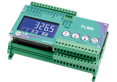 Laumas TLM8 weighing transmitter
 -
 Anybus X-gateway Configuration Manual
 -
 OMRON NJ/NX OPC UA Configuration Guide
 -
 OMRON NX series system unit power configuration and troubleshooting
 -
 FANUC 16i/18i/21i hardware connection and troubleshooting
 -
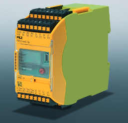 PILZ PNOZmulti Safety Controller Maintenance Guide
 -
 MITSUBISHI ELECTRIC MELSEC A-series PLC Hardware Maintenance and Troubleshooting
 -
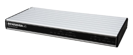 Installation and troubleshooting of Renishaw PHC10-3 PLUS controller
 -
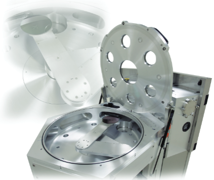 Constellation HA Series Vacuum Transmission System Selection Guide
 -
 PILZ PNOZ m B0 configurable safety control system basic unit
 -
 BANNER BES58-6 series incremental encoder selection and troubleshooting guide
 -
 Classic PLC Maintenance: Practical Memory and I/O Configuration
 -
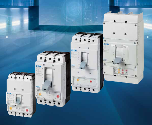 Eaton LZM Circuit Breaker Selection and Engineering Guide
 -
 Pilz PSWZ X1P static monitoring
 -
 Keyence CV-3000 Visual System Selection
 -
 Pro face GP2000 Maintenance Guide
 -
 Siemens S120 frequency converter maintenance and configuration
 -
 Allen Bradley InterBus Module Configuration Guide
 -
 MX321 AVR Voltage Regulator Guide
 -
 GE MM2 Motor Manager Complete Guide
 -
 SIEMENS C500 microcontroller architecture and instruction set
 -
 HORIBA SEC-Z500X Mass Flow Controller
 -
 QUBE Servo 2 Teaching Experiment Platform
 -
 Schneider TSX17 serial communication upgrade and replacement
 -
 GE DC Drives (BCH series) upgrade and replacement of old DC drives
 -
 Honeywell X-DCS3000 Digital Integrated System Manager
 -
 OMRON Z500 high-precision contour measurement system
 -
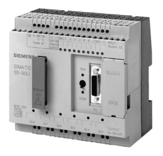 Siemens SIMATIC S5-90U/S5-95U Compact PLC
 -
 KEB F5 Elevator Driver Complete Guide
 -
 TOSHIBA VF-S15 Inverter Complete Guide
 -
 Complete Guide to SV-iG5A Inverter
 -
 Allen Bradley Guard PLC Safety System Practical Guide
 -
 Omron C1000H/C2000H PLC Practical Guide
 -
 Omron F160-2 Visual Expert Guide
 -
 Bonner Q45U Ultrasonic Sensor in Practical Use
 -
 Schneider C60H-DC Protector Practical Manual
 -
 Omron CPM2B Board PLC Practical Guide
 -
 Omron C500 PLC Installation and Maintenance Guide
 -
 Mitsubishi FXo/FXon PLC Hardware Practice
 -
 PULS QS40.241 Power Supply Practical Guide
 -
 Eaton XV-102-L Touchscreen Installation Guide
 -
 Omron FZ5 Vision System Selection and Configuration Guide
 -
 Schneider TSX47 series PLC selection
 -
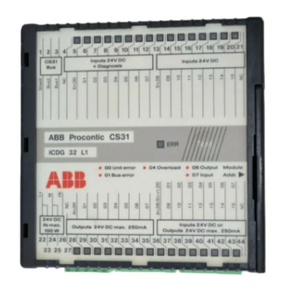 ABB CS31 distributed debugging
 -
 OMRON H8PR electronic cam debugging
 -
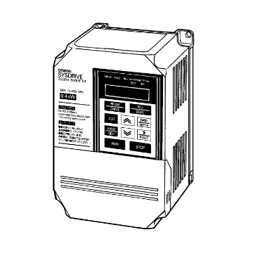
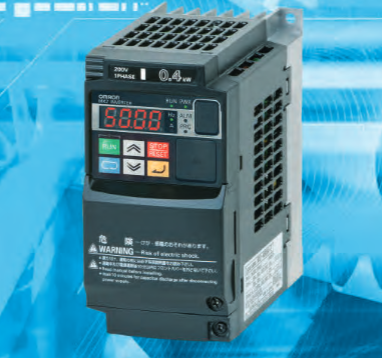 OMRON MX2 frequency converter debugging
 -
 GP477R Engineering Installation
 -
 Siemens AS-i SlimLine Diagnostic Guidelines
 -
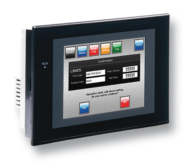 OMRON NS Series PT Remote Access
 -
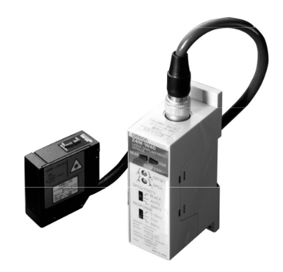 OMRON Z4M sensor precision measurement
 -
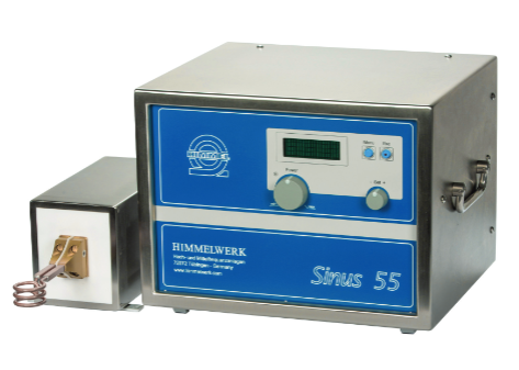 HIMMERWERK SINUS High Frequency Induction Heating Selection
 -
 OMRON CP1E PLC Practical Selection Guide
 -
 OMRON ZFX-C Vision Sensor in Practical Use
 -
 OMRON ZFV Intelligent Sensor Practical Guide
 -
 OMRON CJ Series PLC Practical Guide
 -
 Murr SIRCO Isolation Switch Selection Guide
 -
 OMRON ZFX Vision Sensor Engineering Practice
 -
 REER ULISSE UNC Security Light Curtain Practice
 -
 Siemens S5-90U/95U Fault Diagnosis and Advanced Programming
 -
 OMRON CPM2C system fault diagnosis and maintenance
 -
 Yaskawa ∑ - V Servo Drive Debugging Guide
 -
 OMRON CP1H PLC Practical Manual
 -
 OMRON K-type PLC Maintenance Guide
 -
 PEPPERL+FUCHS SLVA-4Kplus Safety Light Curtain Guide
 -
 Yaskawa ∑ - II Servo Drive Debugging Guide
 -
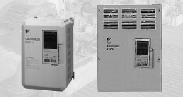 Yaskawa VS-616PC5/P5 frequency converter practical application
 -
 OMRON 3G3SV Inverter Practical Manual
 -
 Pro face GP370 Complete Guide
 -
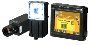 OMRON FQ2 Smart Camera Selection Guide
 -
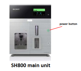 Practical Guide to Sony SH800 Sorter
 -
 OMRON Cam Positioner Complete Guide
 -
 KEB F4 Inverter Debugging Guide
 -
 OMRON CJ series PLC operation and maintenance essentials
 -
 Essentials of Schneider C60H-DC DC DC Protector
 -
 OMRON 3G3MV Inverter Practical Guide
 -
 Essentials of OMRON CQM1H PLC System
 -
 Essentials of ARD Elevator Emergency Rescue Device
 -
 SolaHD SDN-D rail power supply
 -
 OMRON C200H PLC Troubleshooting and Programming Essentials
 -
 Allen Bradley 1336 PLUS Inverter Practical Guide
 -
 OMRON 3G3KV frequency converter
 -
 OMRON NSJ Integrated Controller
 -
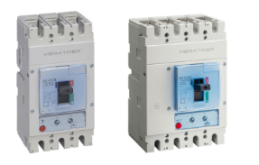 Megatiker M4 Circuit Breaker Maintenance
 -
 OMRON ZX laser sensor maintenance
 -
 Saia PCD1 Controller Maintenance Guide
 -
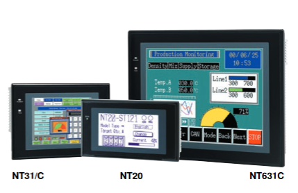 OMRON NT Series HMI Replacement and Maintenance
 -
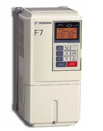 Yaskawa F7 Driver Maintenance and Replacement
 -
 Rockwell 1494 switch selection replacement
 -
 Omron NA Series HMI Connection Guide
 -
 Eaton CV Series PLC System Upgrade and Diagnosis
 -
 Eaton XV-102 HMI Installation and Troubleshooting
 -
 Siemens SINUMERIK measurement cycle configuration
 -
 ELAU PacDrive C600 Controller Integration Guide
 -
 ELAU PacDrive SM Servo Motor Application and Maintenance Guide
 -
 Bently Nevada Orbit 60 System Upgrade and Troubleshooting Guide
 -
 YOKOGAWA STARDOM FCN-RTU Controller
 -
 Fireye InSight II Marine Flame Scanner
 -
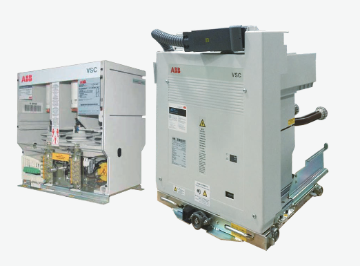 How to install ABB VSC vacuum contactor?
 -
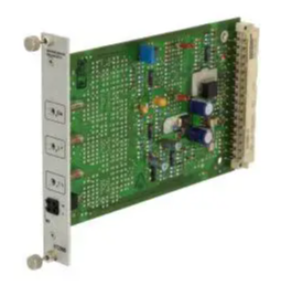 Rexroth Bosch Group VT2000 Proportional Amplifier
 -
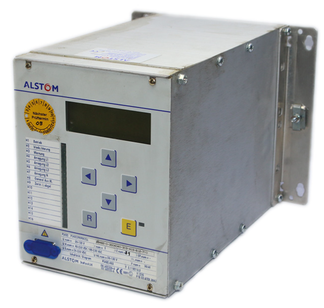 ALSTOM ALSPA series frequency converter
 -
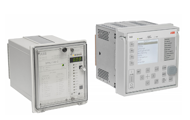 ABB SPACOM replaces REX615
 -
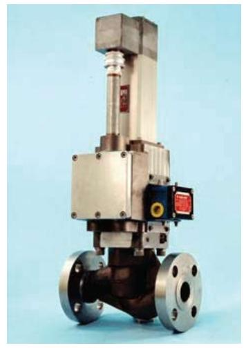 Meggitt C327895 Gas Metering Valve Technology
 -
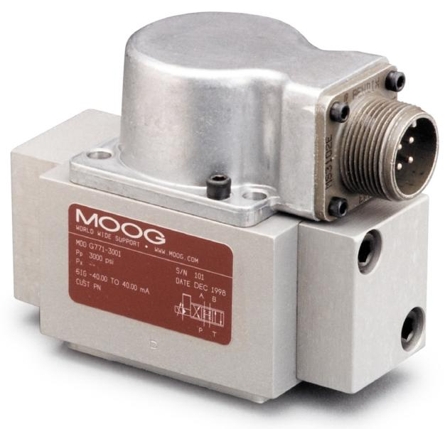 Application of MOOG G77x servo valve
 -
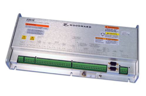 WOODWARD 2301E Digital Speed Controller
 -
 ABB UNITOL 1010/1020 AVR Compact IGBT Automatic Voltage Regulator
 -
 ABB UNITOL 6000 excitation system
 -
 Rexroth Bosch Group HNC100 Hydraulic Shaft Control
 -
 Lenze 8400 Inverter Debugging Guide
 -
 Panning Vacuum Sensor Maintenance Guide
 -
 SOGEVAC Rotary Disc Pump Maintenance Guide
 -
 THERMOVAC MEMS Vacuum Gauge Guide
 -
 TTR 101 Vacuum Gauge Troubleshooting Guide
 -
 Honeywell Beam Smoke Detector Guide
 -
 TURBOVAC Molecular Pump Maintenance Guide
 -
 Troubleshooting of Leuze electronic DDLS 200 optical transmission
 -
 Lam Harmonic Drive Quick Replacement Guide
 -
 LZS power replacement and troubleshooting
 -
 MTL2000 series isolation barrier
 -
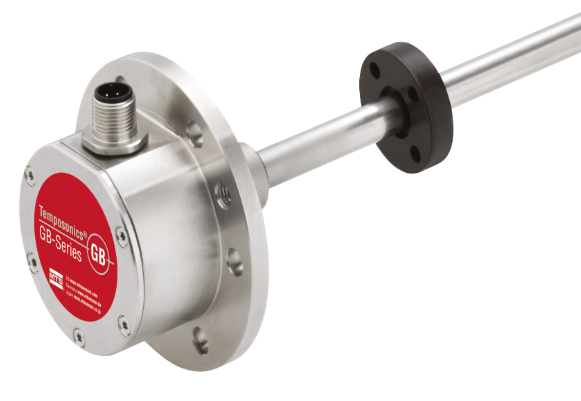 Temposonics GB Sensor
 -
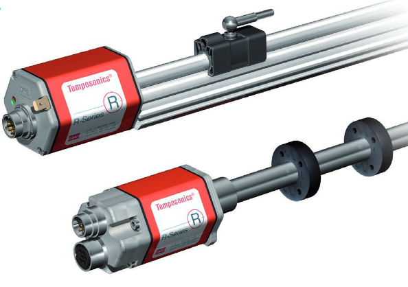 Temposonics R Series Magnetostrictive Displacement Sensor Depth
 -
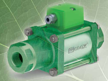 Original inventor of M ü ller Co ax AG coaxial valve
 -
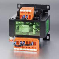 Murrelektronik Automation Solution Complete Solution
 -
 Nabtesco RV series high-precision gearbox
 -
 NACHI Robot Full Series
 -
 Electro hydraulic proportional directional flow valve
 -
 NEC FC-9801X Industrial Computer
 -
 Mark VIeS Security System


