
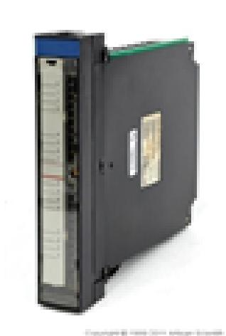
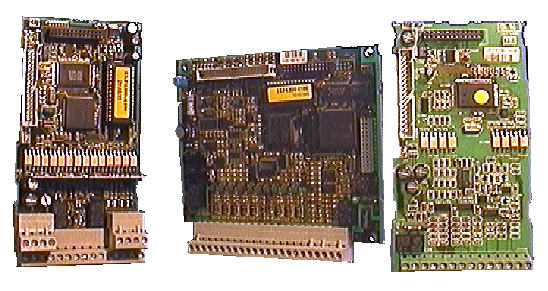
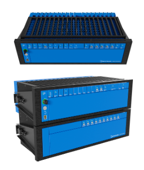
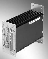
FORCE CPU-2CE/16 is an embedded central processing unit module designed by FORCE COMPUTERS (later under Emerson) specifically for industrial high reliability scenarios. It features VMEbus compatibility and strong environmental adaptability, and is widely used in fields such as industrial automation control, military electronic equipment, and rail transit signal processing that require high stability and real-time performance. This module is designed with modular card insertion as its core, integrating high-performance processing architecture, flexible storage expansion capabilities, and rich interface configurations. At the same time, through industrial grade component selection and anti-interference design, it ensures long-term continuous and stable operation under complex working conditions.
FORCE CPU-2CE/16 Industrial Control CPU Module
FORCE CPU-2CE/16 is an embedded central processing unit module designed by FORCE COMPUTERS (later under Emerson) specifically for industrial high reliability scenarios. It features VMEbus compatibility and strong environmental adaptability, and is widely used in fields such as industrial automation control, military electronic equipment, and rail transit signal processing that require high stability and real-time performance. This module is designed with modular card insertion as its core, integrating high-performance processing architecture, flexible storage expansion capabilities, and rich interface configurations. At the same time, through industrial grade component selection and anti-interference design, it ensures long-term continuous and stable operation under complex working conditions.
Core hardware architecture and performance parameters
1. High performance processing core
The FORCE CPU-2CE/16 adopts two mainstream architecture configurations (subdivided according to specific models): one is the classic Motorola 68020/68030 processor architecture, with a basic clock frequency of 16MHz, which has efficient processing capabilities with a simplified instruction set. It can complete multiple basic operation instructions in a single cycle and is suitable for real-time logical operation requirements in the industrial control field; The second is Sun Microsystems' SPARC Classic processor architecture (some models), with a clock speed increased to 40MHz, further enhancing multitasking parallel processing capabilities. Both architectures support floating-point coprocessor extensions (such as MC68881/MC68882), which can significantly improve the processing efficiency of complex mathematical operations, scientific calculations, and high-precision control algorithms, meeting high-performance requirements such as industrial robot motion control and precision instrument measurement.
2. Storage system design
The module adopts an independent partition design of "program storage+data storage", supports multiple storage media expansion, and balances storage stability and flexibility: the basic configuration includes 16MB onboard DRAM memory (some models can be expanded to 32MB), which is used for real-time data caching and program running space, ensuring response speed when multitasking is concurrent; Program storage supports both EPROM and Flash media, with Flash storage supporting online flashing and program updates, facilitating on-site system upgrades and maintenance; Simultaneously reserve DRM memory expansion module interface, which can expand storage capacity according to application scenario requirements, adapt to large control programs and massive real-time data storage needs. The storage system has parity check function, which can detect and correct errors in the data transmission process in real time, and improve the reliability of data storage.
3. Bus and interface configuration
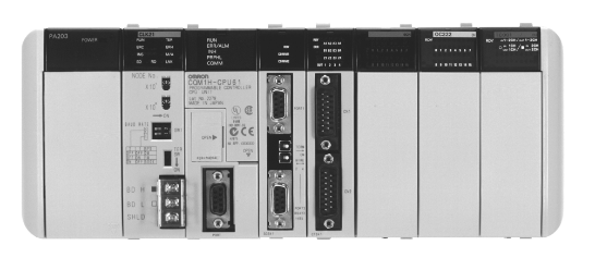
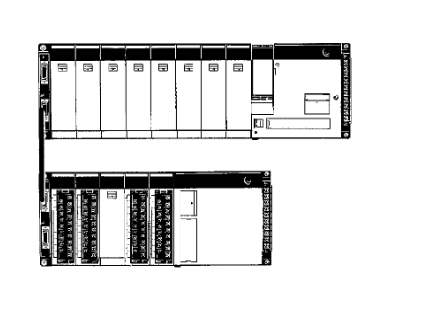
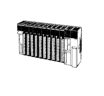
Bus compatibility is one of the core advantages of this module, which fully complies with the VMEbus industrial bus standard and adopts a single slot 6U VME board design. It can seamlessly integrate into various VME bus systems and serve as the main control CPU module to achieve high-speed data exchange with I/O expansion modules, communication modules, acquisition modules, etc. It supports multi board collaborative work and distributed computing architecture, and adapts to the modular integration requirements of large industrial control systems.
Rich interface configuration that balances universality and professionalism: 4 industrial grade serial ports (RS-232/RS-485), supporting point-to-point communication with underlying devices such as PLCs, sensors, and actuators, with anti electromagnetic interference capabilities, suitable for long-distance data transmission in industrial sites; Two parallel ports can be directly connected to external devices such as printers and industrial display screens for data output and status display; Reserved PCIe 3.0 x16 high-speed interface (some models), supporting access to high-performance graphics processing modules or high-speed storage devices, suitable for graphics intensive industrial monitoring scenarios; In addition, it also integrates Ethernet SCSI、 Keyboard interface, etc., can achieve remote control, connection of large capacity storage devices, and local operation interaction, fully covering various interface requirements of industrial control.
Software Ecology and System Adaptation
FORCE CPU-2CE/16 has complete software compatibility and can adapt to various industrial grade real-time operating systems (RTOS) and multitasking operating systems, providing a flexible software platform for application development. The core supports mainstream real-time operating systems such as VxWorks and OS-9, which have the characteristics of micro core architecture, low task scheduling delay, and fast interrupt response speed, ensuring the real-time and deterministic nature of industrial control tasks, and are suitable for scenarios such as precise control of assembly lines and real-time response to equipment failures; Simultaneously compatible with UNIX operating system, supports complex network protocols and multi-user management, and adapts to distributed control systems that require remote monitoring and multi terminal collaboration.
The module provides a complete software development toolchain, including compilers, debuggers, driver libraries, etc. It supports mainstream programming languages such as C and C++, making it easy for developers to develop, debug, and port applications. In addition, manufacturers provide detailed technical manuals and driver support, which can significantly reduce the difficulty of system integration and shorten the project development cycle.
Industrial grade reliability design
1. Adaptability to harsh environments
The module adopts industrial grade high reliability component selection, and all chips undergo environmental stress screening such as high temperature, low temperature, and humidity cycling. It can work stably in a wide temperature range of -40 ℃~85 ℃ and is suitable for extreme environments such as high temperature industrial workshops and low temperature outdoor equipment rooms; Has strong anti electromagnetic interference capability, certified by EMC (Electromagnetic Compatibility), can resist electromagnetic radiation interference generated by industrial field frequency converters, motors and other equipment, ensuring the stability of data transmission and operation; Simultaneously adopting anti vibration and anti impact design, the board adopts reinforced PCB design, and the components adopt mounting technology and add protective glue, which can withstand the vibration and impact during the operation of industrial equipment, suitable for mobile working conditions such as rail transit and ship electronics.
2. Redundant and fault-tolerant design
The module supports redundant power supply access and can be connected to dual power supply modules. When one power supply fails, the other power supply can seamlessly switch power supply to avoid system shutdown caused by power failure; Some models support dual machine hot standby function, which achieves real-time data synchronization between two CPU modules through a dedicated interface. When the main module fails, the standby module can immediately take over the control task, ensuring the continuous operation of the system and improving the availability of industrial control systems.
Installation and maintenance specifications
1. Installation precautions
Before installation, it is necessary to ensure that the working environment meets the requirements: stay away from heat sources, water sources, and strong electromagnetic radiation sources, and choose the installation location with the least vibration; Reserve sufficient heat dissipation space (it is recommended to reserve at least 5cm space on both sides of the board) to ensure the normal operation of the heat dissipation fan. During the installation process, it is necessary to strictly follow the ESD (electrostatic protection) specifications, wear an anti-static wristband, and avoid directly touching the chips and gold fingers on the board; When inserting into the VME bus slot, align the slot guide rail, slowly push in, and strictly prohibit violent pressing to ensure good contact between the board and the slot; When fixing, use bolts of specified specifications (M6 bolts are recommended) to ensure that the board is securely installed and avoid poor contact caused by vibration.
Attention should be paid when wiring: first disconnect the system power supply, and then connect the cables; The power wiring should strictly distinguish between positive and negative poles to avoid module damage caused by reverse connection; The grounding wire should use a wire with a specification of IV-8 sq to ensure good grounding of the board and reduce electromagnetic interference; If multiple expansion modules need to be connected, they should be wired in the order required by the manual to avoid signal conflicts.
2. Daily maintenance and troubleshooting
Regular visual inspection is required for daily maintenance: check whether the board has bulges or burn marks, whether the cooling fan is running normally, and whether the cable connections are firm; Regularly clean the dust on the surface of the board to avoid dust accumulation and poor heat dissipation. During the maintenance process, it is necessary to strictly follow safety regulations: first disconnect the main power supply and all external energy sources, remove the main input cable, wait for 5 minutes to ensure that the intermediate circuit is completely discharged before proceeding with the operation; It is strictly prohibited to modify software security configuration parameters (such as force limit, interrupt priority, etc.) without authorization. If modifications are necessary, a new risk assessment and security audit must be conducted.
Common troubleshooting: If the module cannot be started, first check whether the power status and supply voltage are normal, and whether the power indicator light is on; If the power supply is normal, you can enter the BIOS interface to check the hardware recognition status and confirm whether the memory, hard disk, and other devices are recognized. If not recognized, it may be due to poor hardware contact or malfunction, and components need to be unplugged or replaced; If an error occurs after system startup, you can refer to the error code in the manual to locate the cause of the fault, and prioritize using the replacement method to troubleshoot the faulty component (it is recommended to use the same model or equivalent components recognized by the manufacturer for replacement). All maintenance operations must be recorded in detail and archived in the system technical documentation for easy traceability in the future.
- User name Member Level Quantity Specification Purchase Date
- Satisfaction :
-


-
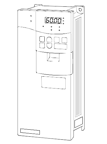 MITSUBISHI ELECTRIC FR-A500 frequency converter
 -
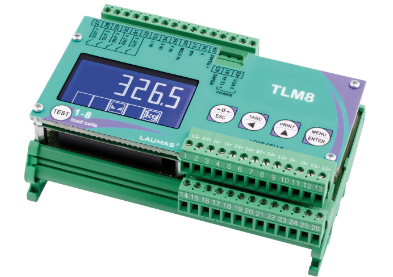 Laumas TLM8 weighing transmitter
 -
 Anybus X-gateway Configuration Manual
 -
 OMRON NJ/NX OPC UA Configuration Guide
 -
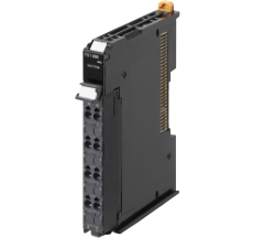 OMRON NX series system unit power configuration and troubleshooting
 -
 FANUC 16i/18i/21i hardware connection and troubleshooting
 -
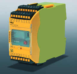 PILZ PNOZmulti Safety Controller Maintenance Guide
 -
 MITSUBISHI ELECTRIC MELSEC A-series PLC Hardware Maintenance and Troubleshooting
 -
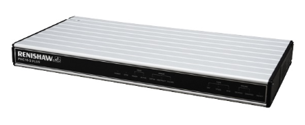 Installation and troubleshooting of Renishaw PHC10-3 PLUS controller
 -
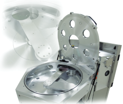 Constellation HA Series Vacuum Transmission System Selection Guide
 -
 PILZ PNOZ m B0 configurable safety control system basic unit
 -
 BANNER BES58-6 series incremental encoder selection and troubleshooting guide
 -
 Classic PLC Maintenance: Practical Memory and I/O Configuration
 -
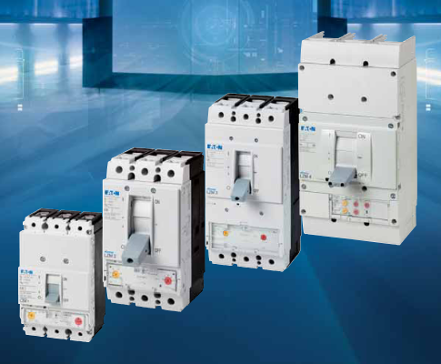 Eaton LZM Circuit Breaker Selection and Engineering Guide
 -
 Pilz PSWZ X1P static monitoring
 -
 Keyence CV-3000 Visual System Selection
 -
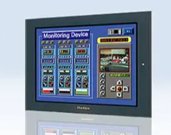 Pro face GP2000 Maintenance Guide
 -
 Siemens S120 frequency converter maintenance and configuration
 -
 Allen Bradley InterBus Module Configuration Guide
 -
 MX321 AVR Voltage Regulator Guide
 -
 GE MM2 Motor Manager Complete Guide
 -
 SIEMENS C500 microcontroller architecture and instruction set
 -
 HORIBA SEC-Z500X Mass Flow Controller
 -
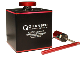 QUBE Servo 2 Teaching Experiment Platform
 -
 Schneider TSX17 serial communication upgrade and replacement
 -
 GE DC Drives (BCH series) upgrade and replacement of old DC drives
 -
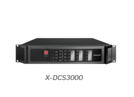 Honeywell X-DCS3000 Digital Integrated System Manager
 -
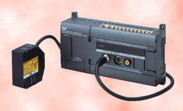 OMRON Z500 high-precision contour measurement system
 -
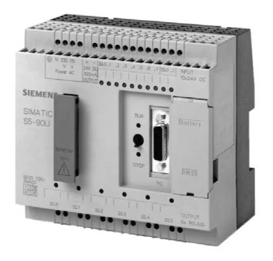 Siemens SIMATIC S5-90U/S5-95U Compact PLC
 -
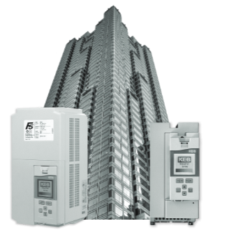 KEB F5 Elevator Driver Complete Guide
 -
 TOSHIBA VF-S15 Inverter Complete Guide
 -
 Complete Guide to SV-iG5A Inverter
 -
 Allen Bradley Guard PLC Safety System Practical Guide
 -
 Omron C1000H/C2000H PLC Practical Guide
 -
 Omron F160-2 Visual Expert Guide
 -
 Bonner Q45U Ultrasonic Sensor in Practical Use
 -
 Schneider C60H-DC Protector Practical Manual
 -
 Omron CPM2B Board PLC Practical Guide
 -
 Omron C500 PLC Installation and Maintenance Guide
 -
 Mitsubishi FXo/FXon PLC Hardware Practice
 -
 PULS QS40.241 Power Supply Practical Guide
 -
 Eaton XV-102-L Touchscreen Installation Guide
 -
 Omron FZ5 Vision System Selection and Configuration Guide
 -
 Schneider TSX47 series PLC selection
 -
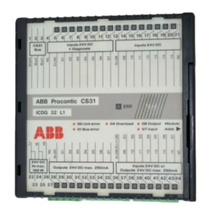 ABB CS31 distributed debugging
 -
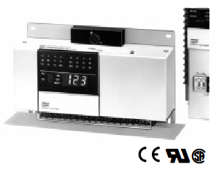 OMRON H8PR electronic cam debugging
 -
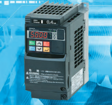 OMRON MX2 frequency converter debugging
 -
 GP477R Engineering Installation
 -
 Siemens AS-i SlimLine Diagnostic Guidelines
 -
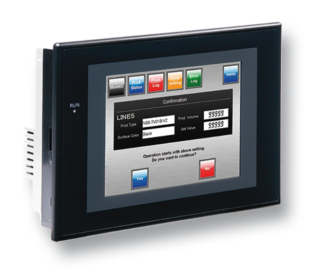 OMRON NS Series PT Remote Access
 -
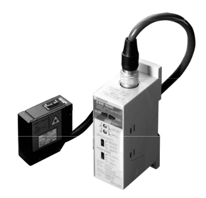 OMRON Z4M sensor precision measurement
 -
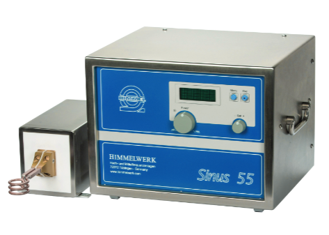 HIMMERWERK SINUS High Frequency Induction Heating Selection
 -
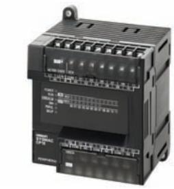 OMRON CP1E PLC Practical Selection Guide
 -
 OMRON ZFX-C Vision Sensor in Practical Use
 -
 OMRON ZFV Intelligent Sensor Practical Guide
 -
 OMRON CJ Series PLC Practical Guide
 -
 Murr SIRCO Isolation Switch Selection Guide
 -
 OMRON ZFX Vision Sensor Engineering Practice
 -
 REER ULISSE UNC Security Light Curtain Practice
 -
 Siemens S5-90U/95U Fault Diagnosis and Advanced Programming
 -
 OMRON CPM2C system fault diagnosis and maintenance
 -
 Yaskawa ∑ - V Servo Drive Debugging Guide
 -
 OMRON CP1H PLC Practical Manual
 -
 OMRON K-type PLC Maintenance Guide
 -
 PEPPERL+FUCHS SLVA-4Kplus Safety Light Curtain Guide
 -
 Yaskawa ∑ - II Servo Drive Debugging Guide
 -
 Yaskawa VS-616PC5/P5 frequency converter practical application
 -
 OMRON 3G3SV Inverter Practical Manual
 -
 Pro face GP370 Complete Guide
 -
 OMRON FQ2 Smart Camera Selection Guide
 -
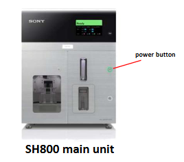 Practical Guide to Sony SH800 Sorter
 -
 OMRON Cam Positioner Complete Guide
 -
 KEB F4 Inverter Debugging Guide
 -
 OMRON CJ series PLC operation and maintenance essentials
 -
 Essentials of Schneider C60H-DC DC DC Protector
 -
 OMRON 3G3MV Inverter Practical Guide
 -
 Essentials of OMRON CQM1H PLC System
 -
 Essentials of ARD Elevator Emergency Rescue Device
 -
 SolaHD SDN-D rail power supply
 -
 OMRON C200H PLC Troubleshooting and Programming Essentials
 -
 Allen Bradley 1336 PLUS Inverter Practical Guide
 -
 OMRON 3G3KV frequency converter
 -
 OMRON NSJ Integrated Controller
 -
 Megatiker M4 Circuit Breaker Maintenance
 -
 OMRON ZX laser sensor maintenance
 -
 Saia PCD1 Controller Maintenance Guide
 -
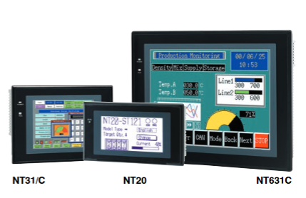 OMRON NT Series HMI Replacement and Maintenance
 -
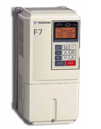 Yaskawa F7 Driver Maintenance and Replacement
 -
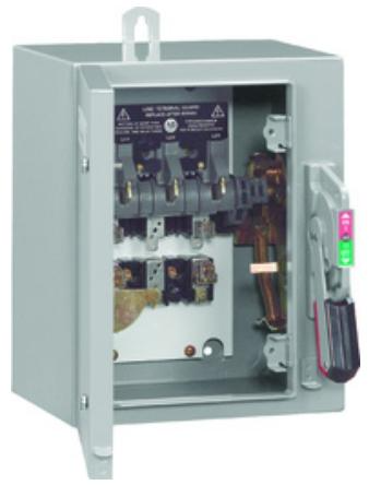 Rockwell 1494 switch selection replacement
 -
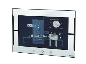 Omron NA Series HMI Connection Guide
 -
 Eaton CV Series PLC System Upgrade and Diagnosis
 -
 Eaton XV-102 HMI Installation and Troubleshooting
 -
 Siemens SINUMERIK measurement cycle configuration
 -
 ELAU PacDrive C600 Controller Integration Guide
 -
 ELAU PacDrive SM Servo Motor Application and Maintenance Guide
 -
 Bently Nevada Orbit 60 System Upgrade and Troubleshooting Guide
 -
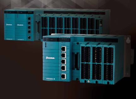 YOKOGAWA STARDOM FCN-RTU Controller
 -
 Fireye InSight II Marine Flame Scanner
 -
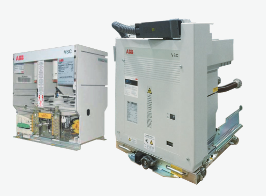 How to install ABB VSC vacuum contactor?
 -
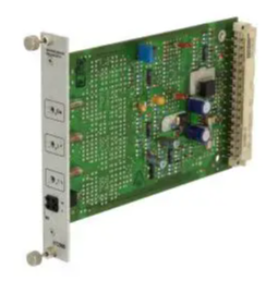 Rexroth Bosch Group VT2000 Proportional Amplifier
 -
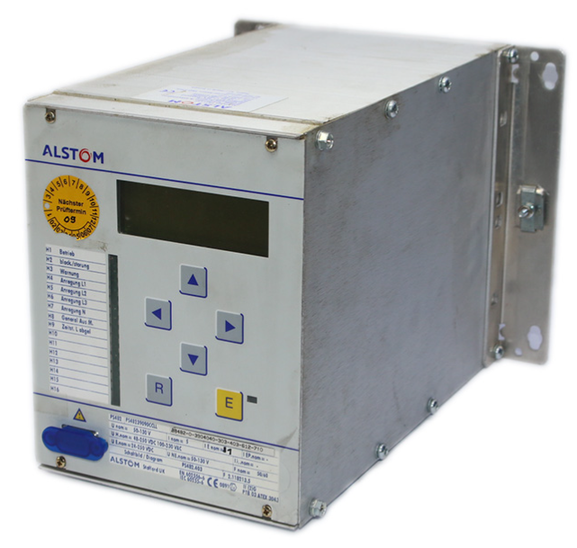 ALSTOM ALSPA series frequency converter
 -
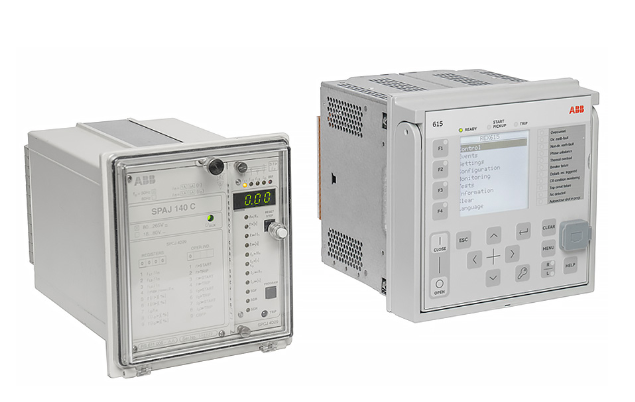 ABB SPACOM replaces REX615
 -
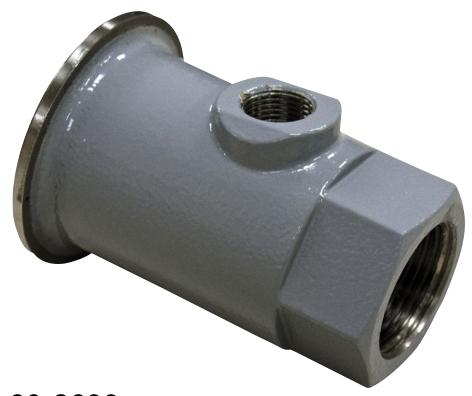
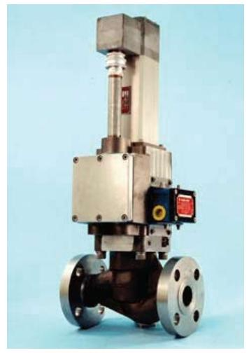 Meggitt C327895 Gas Metering Valve Technology
 -
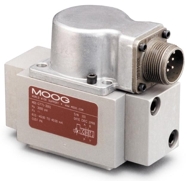 Application of MOOG G77x servo valve
 -
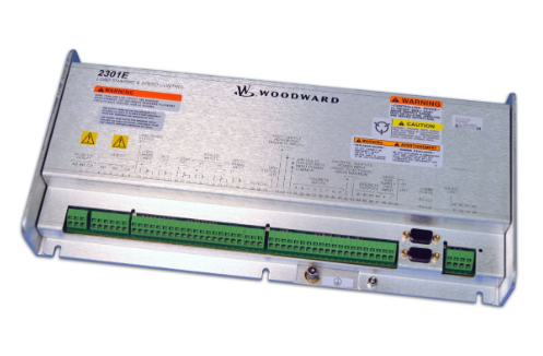 WOODWARD 2301E Digital Speed Controller
 -
 ABB UNITOL 1010/1020 AVR Compact IGBT Automatic Voltage Regulator
 -
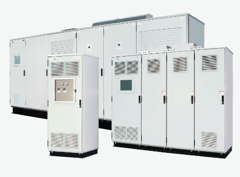 ABB UNITOL 6000 excitation system
 -
 Rexroth Bosch Group HNC100 Hydraulic Shaft Control
 -
 Lenze 8400 Inverter Debugging Guide
 -
 Panning Vacuum Sensor Maintenance Guide
 -
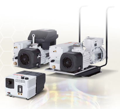 SOGEVAC Rotary Disc Pump Maintenance Guide
 -
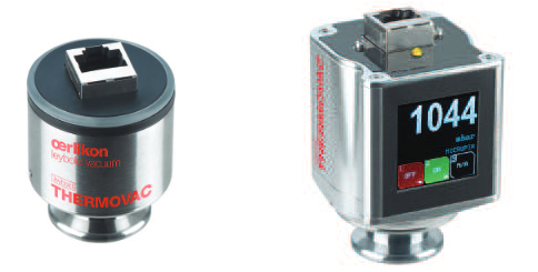 THERMOVAC MEMS Vacuum Gauge Guide
 -
 TTR 101 Vacuum Gauge Troubleshooting Guide
 -
 Honeywell Beam Smoke Detector Guide
 -
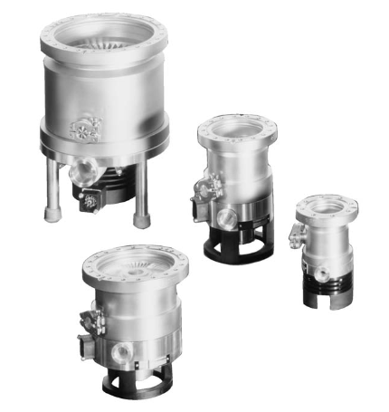 TURBOVAC Molecular Pump Maintenance Guide
 -
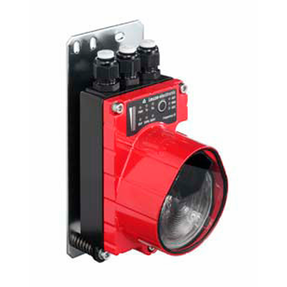 Troubleshooting of Leuze electronic DDLS 200 optical transmission
 -
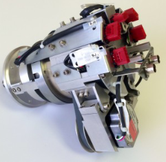 Lam Harmonic Drive Quick Replacement Guide
 -
 LZS power replacement and troubleshooting
 -
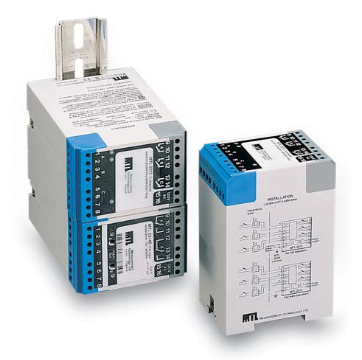 MTL2000 series isolation barrier
 -
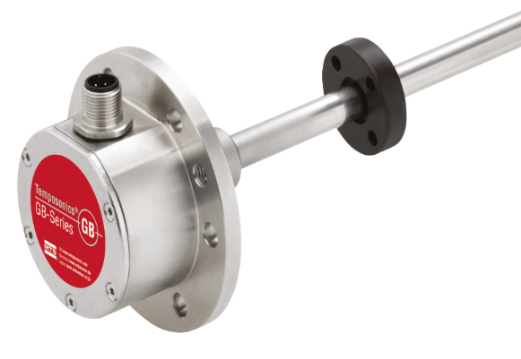 Temposonics GB Sensor
 -
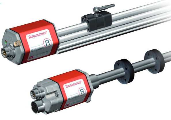 Temposonics R Series Magnetostrictive Displacement Sensor Depth
 -
 Original inventor of M ü ller Co ax AG coaxial valve
 -
 Murrelektronik Automation Solution Complete Solution
 -
 Nabtesco RV series high-precision gearbox
 -
 NACHI Robot Full Series
 -
 Electro hydraulic proportional directional flow valve
 -
 NEC FC-9801X Industrial Computer
 -
 Mark VIeS Security System


