
ABB REF542PLUS 1VCF752000 is an intelligent feeder terminal cabinet designed specifically for medium and high voltage distribution networks. It belongs to the ABB REF series feeder protection products and its core function is to achieve fault protection, real-time monitoring, remote control, and automated operation and maintenance of 10kV-35kV distribution network feeder circuits. It is a key on-site equipment for distribution network automation systems. Its model code follows ABB's power protection product specifications, with "REF542PLUS" as the base model, representing that the terminal cabinet is an upgraded and enhanced version of REF542, integrating more intelligent functions; 1VCF752000 "is a configuration code that covers customized parameters such as cabinet specifications, protection function modules, and communication interface types, adapting to different distribution network topologies and operational requirements.
ABB REF542PLUS 1VCF752000 Feeder Terminal Panel
Product Overview
ABB REF542PLUS 1VCF752000 is an intelligent feeder terminal cabinet designed specifically for medium and high voltage distribution networks. It belongs to the ABB REF series feeder protection products and its core function is to achieve fault protection, real-time monitoring, remote control, and automated operation and maintenance of 10kV-35kV distribution network feeder circuits. It is a key on-site equipment for distribution network automation systems. Its model code follows ABB's power protection product specifications, with "REF542PLUS" as the base model, representing that the terminal cabinet is an upgraded and enhanced version of REF542, integrating more intelligent functions; 1VCF752000 "is a configuration code that covers customized parameters such as cabinet specifications, protection function modules, and communication interface types, adapting to different distribution network topologies and operational requirements.
This terminal cabinet adopts an integrated design, which integrates protection devices, measurement units, control circuits, communication modules, power systems, etc. into a standard cabinet. It can be directly installed at distribution stations and switch stations, and connected to the distribution automation system (DMS) through standardized communication protocols to achieve the "four remote" (telemetry, remote signaling, remote control, remote adjustment) functions of feeders. It provides a full lifecycle solution for the safe and stable operation of distribution networks in fields such as power, municipal, and industrial parks, and is widely used in feeder monitoring and protection scenarios of radial distribution networks and ring network distribution networks.
Specification parameters
Electrical characteristics
System voltage: 10kV/20kV/35kV (suitable for medium and high voltage distribution networks); Current input: 5A/1A (CT secondary side, accuracy level 0.2); Voltage input: 100V (PT secondary side, accuracy level 0.2); Power system: DC 220V/110V (allowable fluctuation ± 20%) or AC 220V (allowable fluctuation ± 15%), equipped with a 220Ah backup battery (endurance ≥ 4h)
Protection function parameters
Overcurrent protection: setting range 0.1-20Ie, action time 0.05-60s (timed/inverse time limit optional); Quick break protection: setting range 1.5-30Ie, action time ≤ 0.04s; zero sequence protection: setting range 0.05-10Ie, action time 0.05-60s; reclosing: supports single-sided/double-sided power supply mode, setting time 0.1-10s, adjustable reclosing times 1-3 times
Measurement and Monitoring
Measurement accuracy: current/voltage level 0.2, power/energy level 0.5, frequency ± 0.01Hz (45-55Hz); Monitoring parameters: three-phase current, three-phase voltage, active power, reactive power, power factor, electrical energy, feeder temperature, cabinet environment temperature and humidity
Communication and Structure
Communication interface: 2 Ethernet ports (10/100M adaptive, supporting IEC 61850-8-1/MMS, IEC 60870-5-104), 1 RS485 port (supporting Modbus RTU); Cabinet specifications: 2200mm x 800mm x 600mm (height x width x depth), protection level IP54 (outdoor type)/IP40 (indoor type); Installation method: Outdoor floor installation (with foundation bracket) or indoor wall mounted installation
Performance characteristics
Full scenario feeder protection capability: covering all types of faults in medium and high voltage distribution network feeders. In addition to basic overcurrent, quick break, and zero sequence protection, it also integrates overload protection (inverse time characteristic in accordance with IEC 60255-4), overvoltage/low voltage protection (setting range 0.8-1.2Un), frequency anomaly protection (47-53Hz), and acceleration protection after reclosing. The protection logic can be flexibly configured according to the distribution network topology (radiation network, ring network, dual power supply) to achieve "accurate identification, rapid isolation, self-healing recovery" of faults and reduce the range and duration of power outages.
High precision measurement and energy efficiency management: using high-precision ADC chips and digital signal processing algorithms, the current and voltage measurement accuracy reaches 0.2 level, and the power and energy can reach 0.5 level. It can collect real-time three-phase electrical parameters and energy loss data of the feeder line, and support forward and reverse active/reactive energy measurement; The built-in line loss analysis function can automatically calculate the line loss (daily/monthly/annual) during the feeder period, providing data support for energy efficiency optimization and reactive power compensation configuration in the distribution network, without the need for additional dedicated metering cabinets.
High reliability and environmental adaptability: The cabinet is made of 304 stainless steel material (outdoor type) or cold-rolled steel plate spray painted (indoor type), which has the ability to resist corrosion, ultraviolet rays, and impact; The internal equipment adopts industrial grade components, and the protection device complies with the IEC 61000-4 series immunity standards (6kV surge immunity, 10V/m electric field immunity), which can resist strong electromagnetic interference and voltage fluctuations in distribution stations; Equipped with a temperature and humidity control system (heating element+fan), ensuring that the internal temperature of the cabinet is -25 ℃~+70 ℃ and the humidity is ≤ 85% RH (no condensation), suitable for harsh outdoor environments such as high temperature, high humidity, and high cold.
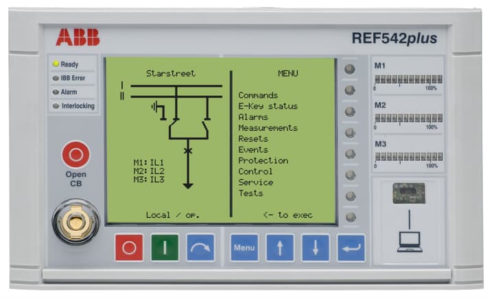
Intelligent operation and digital integration: Native support for IEC 61850 digital protocol, can be directly connected to distribution network automation system (DMS), realizing remote issuance of protection settings, remote retrieval of fault recording, and remote monitoring of equipment status; Built in fault recording function (recording waveforms of 20 cycles before and 40 cycles after the fault, with a sampling rate of 2kHz), supporting COMTRADE format export for easy tracing of fault causes; Equipped with a local human-machine interface (7-inch touch screen), it can intuitively view real-time data, protection events, and fault waveforms. It supports local operations and parameter configuration, greatly improving the convenience of operation and maintenance.
Working principle
The ABB REF542PLUS 1VCF752000 feeder terminal cabinet has the core workflow of "data acquisition logic judgment action execution information exchange", and the specific mechanism is as follows:
Data acquisition stage: The three-phase current and three-phase voltage analog signals of the feeder are obtained through current transformers (CT) and voltage transformers (PT). After internal isolation, filtering, and ADC conversion by the protection device, the analog signals are converted into digital signals; Simultaneously collect switch signals such as circuit breaker opening and closing positions, grounding switch status, cabinet temperature and humidity, battery voltage, etc., and transmit them to the core processor through a photoelectric isolation circuit; The measurement unit synchronously collects electrical parameters, calculates active power, reactive power, electrical energy and other data, and stores them in the local database.
Logic judgment stage: The core processor (based on a dual core 32-bit embedded CPU) analyzes the real-time collected data according to the preset protection setting and control strategy. If the current exceeds the overcurrent setting value and the duration reaches the setting time, or the current instantly exceeds the quick break setting value, it is judged as a short circuit fault and triggers the corresponding protection logic (such as overcurrent trip, quick break trip); If abnormal voltage or frequency is detected, or if the switch status does not match the remote control command, trigger the alarm logic; The reclosing module determines whether to perform reclosing based on the fault type (instantaneous/permanent) (power supply is restored after successful reclosing of instantaneous faults, and accelerated tripping is performed after reclosing of permanent faults).
Action execution stage: When it is determined to be a fault or abnormal state, the protection device sends a trip command to the circuit breaker through the outlet relay (in case of fault), or drives the indicator light and sound and light alarm through the control circuit (in case of abnormality); If the distribution network self-healing function is configured, the terminal cabinet receives fault information from adjacent terminal cabinets through the communication module, collaborates to determine the fault section, automatically controls the action of the section switch and contact switch, and realizes the isolation of the fault section and the restoration of power supply to the non fault section; The power system automatically switches to backup battery power supply when there is an external power outage, ensuring that the protection device and communication module continue to work for ≥ 4 hours
Information exchange stage: The terminal cabinet uploads protection action events (action time, action type, fault parameters), real-time measurement data, and equipment operating status (power status, communication status, cabinet temperature and humidity) to the distribution automation system through Ethernet or RS485; Simultaneously receive remote control commands issued by the system (such as opening and closing circuit breakers, modifying protection settings), and perform corresponding operations; The local touch screen displays real-time operational data and status, supporting on-site query and operation by maintenance personnel, forming a dual management mode of "remote monitoring+local maintenance".
Precautions
Selection and system matching: When selecting, the cabinet configuration should be determined based on the voltage level of the distribution network (10kV/20kV/35kV), CT/PT ratio, and installation environment (outdoor/indoor). For outdoor scenarios, IP54 protection level and stainless steel cabinet should be selected, and the "dual power interlock protection logic" should be enabled for the dual power feeder; When interfacing with the distribution automation system, it is necessary to confirm the communication protocol (IEC 61850/IEC 60870-5-104) and IP address planning to ensure compatibility of data exchange.
Installation and wiring specifications: Outdoor installation requires pouring a concrete foundation (size ≥ 1000mm × 800mm × 300mm), with the top surface of the foundation 300mm above the ground to prevent rainwater immersion; The cabinet grounding system needs to be independently set up, with a grounding resistance of ≤ 4 Ω (protective grounding) and ≤ 10 Ω (lightning protection grounding), and grounding cables using ≥ 50mm ² copper cables; CT secondary side is strictly prohibited from open circuit, PT secondary side is strictly prohibited from short circuit, and polarity (P1/P2 end) should be checked during wiring to avoid measurement errors or protection misoperation; The communication cable adopts shielded twisted pair, with the shielding layer grounded at one end, and is laid away from the power cable (with a spacing of ≥ 30cm).
Debugging and commissioning process: Static debugging is required before commissioning, including checking the power system (main power supply and battery switching are normal), analog input (inputting standard current/voltage signals to verify measurement accuracy), and protection function (simulating overcurrent/short circuit faults, verifying tripping action time and logic); Communication debugging requires testing the stability of the connection with the distribution automation system (continuous 24-hour communication without interruption or packet loss) to ensure the normal functioning of the "four remote" functions; After debugging is completed, lock the protection setting (through password or hardware lock) and record the initial operating data (such as initial energy value, cabinet temperature and humidity).
Maintenance and troubleshooting: Regularly (quarterly) inspect the appearance of the cabinet (for corrosion and deformation), sealing performance (for rainwater infiltration), and grounding connection (for looseness); Check the battery status monthly (voltage ≥ 2.2V/cell, capacity ≥ 80% rated value), and conduct a battery charge and discharge test every six months; If there is a "communication interruption" fault, it is necessary to check the communication cable, IP address configuration, and protocol compatibility; If there is a "protection refusal", it is necessary to check the protection setting, outlet relay, and circuit breaker operating mechanism; Fault repair requires contacting ABB authorized service providers. It is prohibited to disassemble protective devices or modify core parameters on your own.
- User name Member Level Quantity Specification Purchase Date
- Satisfaction :
-


-
 ADLINK cPCI-3720: 3U CompactPCI Low Power Pentium III CPU Module
 -
 ADLINK NuPRO-E47: PICMG 1.3 13th Generation Core Industrial SHB
 -
 ADLINK NuPRO-E43: PICMG 1.3 Core 7th Generation Industrial SHB
 -
 ADLINK NuPRO-780 PICMG Bus Core CPU Card
 -
 ADLINK cPCI-6965 6U CompactPCI Core Dual Core Single Board Computer
 -
 ADLINK USB/LPCI/LPCIe-3488A GPIB Interface Card Selection and Application Guide
 -
 Rittal SK 3241.700 Blue e+Cabinet Fan Filter Unit
 -
 ADLINK CPCI-8168 8-Axis Motion Control Card and HSL Network Integration Solution
 -
 ADLINK PCIe-PXIe-8638 High Speed PXIe Bus Expansion Scheme
 -
 ADLINK PCIe GIE7x Poe+Frame Grabber Hardware and Power Management Detailed Explanation
 -
 ADLINK PCIe-7396 Digital I/O Card Deployment Guide
 -
 ADLINK PCI-8164 Advanced Motion Control Card Deployment Guide
 -
 ADLINK PCI-8154 Motion Control Card Deployment Guide
 -
 ADLINK PCI-8134 Motion Control Card Deployment Guide
 -
 ADLINK NuPRO-E42 Industrial Control Motherboard Deployment Guide
 -
 ADLINK MXC-6600 Embedded Platform Deployment Guide
 -
 ADLINK MXC-6000 Industrial Control Computer Deployment and Optimization Guide
 -
 ADLINK MXC-2300 Embedded System Deployment Guide
 -
 ADLINK MCM-204 Edge DAQ Deployment Configuration Guide
 -
 ADLINK MCM-100/102 Deployment Calibration Guide
 -
 Deployment and Performance Optimization of ADLINK MXC-6400 Industrial Control Computer
 -
 Selection and Deployment of ADLINK Matrix Series Industrial Control Computers
 -
 российские промышленные новые машины.Наш отдел дебютировал в 2026 году в России Международная промышленная ярмарка INNOPROM
 -
 Deeply cultivating the Eurasian industrial market, linking new industrial opportunities between China and Russia
 -
 Deployment and troubleshooting of ADLINK GIE64+PoE acquisition card
 -
 Honeywell UMS Security System Troubleshooting Guide
 -
 Honeywell Expert Series C I/O Troubleshooting Guide
 -
 ADLINK EOS-1200 Vision System Deployment and Troubleshooting
 -
 ADLINK DLAP-5200 series AI engine deployment and optimization
 -
 ADLINK DLAP-4000 Deployment and BIOS Optimization
 -
 ADLINK Matrix MXC-2000 Deployment and Troubleshooting
 -
 ADLINK DAQe-2000 series acquisition card calibration and synchronization
 -
 ADLINK cPCI-6520 Core i7 Processor Blade Engineering Application Guide
 -
 ADLINK CM1-86DX3 PC/104 Embedded Single Board Computer Engineering Application Guide
 -
 Honeywell DC1000 Series PID Temperature Controller Engineering Application Guide
 -
 ALSTOM MiCOM C264 Substation Controller Engineering Application Guide
 -
 EMERSON AMS 2140 Practical Guide for On site Dynamic Balance and Vibration Analysis
 -
 ADLINK NuPRO-E320 motherboard deployment and tuning guide
 -
 ADLINK NuPRO-800 Dual PIII Industrial SBC Maintenance and Upgrade Guide
 -
 ADLINK NuPRO-598 SBC Maintenance Practical Guide
 -
 ADLINK MXC-6300 Fanless Embedded Industrial Control Computer Deployment Guide
 -
 ADLINK Express-BASE7 Carrier Board Quick Deployment and Debugging Guide
 -
 ADLINK DLAP-211 Edge AI Platform Selection and Deployment Guide
 -
 ADLINK 7230 Series Isolation DIO Card Selection and Engineering Application Guide
 -
 ADLINK cPCI-6965 SBC Embedded Installation and BIOS Tuning Guide
 -
 ADLINK 7200 Series High Speed DIO Card Practical Guide
 -
 ADLINK DLAP Series Edge AI Acceleration Platform Selection and Deployment Practical Guide
 -
 DEIF TCM-2 thyristor control module: Wind power cut in control engineering guide
 -
 DEIF MVR-200 Medium Voltage Relay: Installation and Wiring Engineering Guide
 -
 DEIF MDR-2 Differential Relay: Engineering Guide for Generator Differential Protection
 -
 DEIF Delomatic 3 AOM: Engineering Guide for Analog Output Modules
 -
 DEIF AGI 400 Graphic Interface: Ship and Industrial HMI Solution
 -
 DEIF BRW-1 Marine Instruments: Installation and Calibration Guide for Offshore Bridge Indicators
 -
 DEIF AGC 200 Controller: Quick Deployment and Configuration Guide for Generator Sets
 -
 DEIF AGC-2 Controller: The Ultimate Guide to Automatic Control and Protection of Generator Sets
 -
 ABB SPA-ZC400 Gateway: REM54x Access to IEC 61850 Ultimate Engineering Guide
 -
 ABB REM 543/545 Terminal
 -
 Modular Architecture Analysis of DEIF PPU 300 Ship Generator Controller
 -
 DEIF DM-4 Marine&Offshore Ship Power Management System
 -
 Detailed Explanation of DEIF Delomatic Generator Control System Architecture
 -
 DEIF AGC-4 Mk II Generator Controller Depth Configuration Guide
 -
 DEIF AGC-4 Generator Controller Configuration and Debugging Guide
 -
 DEIF PPM Power Management System Operation and Troubleshooting
 -
 Installation and wiring of DEIF Multi line 2
 -
 Practical configuration and maintenance of Beckwith M-6280 capacitor bank controller
 -
 Beckwith M-3311 Transformer Protection Relay Setting and Engineering Application
 -
 Beckwith M-3311A Transformer Protection Relay Configuration and Optimization Guide
 -
 Beckwith M-3310 Transformer Protection Relay Complete Guide
 -
 Beckwith M-0359 synchronous inspection relay
 -
 Beckwith M-0293A Voltage Regulating Controller Replacement and Debugging Guide
 -
 Complete Guide to DEIF GPU-3 Generator Protection Unit
 -
 Installation and I/O configuration of DEIF PPM-3 power management module
 -
 Beckwith M-3520 Interconnection Protection Relay
 -
 Beckwith M-3430 Generator Protection Relay
 -
 Beckwith M-2293B adapter panel replacement GE regulator guide
 -
 Selection and Networking of Beckwith M-2001C Digital Voltage Regulating Controller
 -
 Beckwith M-2001B Digital Voltage Regulating Controller
 -
 Beckwith M-0388/M-0389 Synchronous Inspection Relay Application Guide
 -
 Beckwith M-0193B Synchronizer Debugging and System Integration Guide
 -
 Beckwith M-0115A Parallel Balance Module Debugging Guide
 -
 Beckwith M-0067E On Load Voltage Regulating Controller Selection and Debugging Guide
 -
 Debugging and Fault Handling of Beckwith M-4272 Digital Busbar Conversion System
 -
 Beckwith M-3311A Transformer Protection Relay Debugging Guide
 -
 Beckwith M-3425A Generator Protection Relay Debugging Guide
 -
 Setting and troubleshooting of Basler BE1-27/59 voltage relay
 -
 Debugging and troubleshooting of Basler AVC63-12/AVC125-10 voltage regulator
 -
 Basler L301kc Line Array Camera Technology and Troubleshooting
 -
 Selection and Debugging of Basler CBS 212A Current Boosting System
 -
 Selection and commissioning of Basler BE3-25 synchronous inspection relay
 -
 Basler BE1-32R/32O/U Direction Power Relay Setting and Testing Guide
 -
 Basler PRS 250 Synchronous Relay Maintenance and Replacement Guide
 -
 Basler piA2400-17gc Industrial Camera Replacement and Optimization Guide
 -
 Basler BE1-11g Generator Protection System
 -
 Basler VR63-4C/UL Voltage Regulator
 -
 Basler BE1-DFPR feeder protection relay
 -
 Basler CBS 310/320 Current Boosting System
 -
 Basler UFOV 250A/260A protection module
 -
 Basler MVC104/MVC108/MVC232 manual voltage control device
 -
 Basler XR2002/XR2002F Regulator
 -
 Basler DECS-400 excitation system
 -
 Basler DGC-2020 Generator Set Controller: Integrated Control and Debugging Guide
 -
 Basler MVC-300 Manual Voltage Controller: Characteristics and Engineering Applications
 -
 Basler MVC Series Manual Voltage Controller: Application and Selection
 -
 Basler SSR Static Voltage Regulator: A Complete Guide to Debugging and Troubleshooting
 -
 Basler SR4A/SR8A Voltage Regulator: Detailed Debugging and Troubleshooting Explanation
 -
 Basler BE2000E Voltage Regulator: Replacement and Application Details
 -
 Basler DECS-2100 Excitation System: Modular Upgrade and Engineering Application
 -
 Basler BE1-851 Overcurrent Protection System: A Complete Guide to Professional Debugging and Troubleshooting
 -
 Basler APR 63-5 Voltage Regulator: Professional Debugging and Troubleshooting Guide for Industrial Generator Excitation Systems
 -
 Basler BE1-FLEX Protection System: A Complete Guide to Professional Installation, Configuration, and Troubleshooting
 -
 Debugging and Testing of Basler BE1-700 Relay
 -
 Basler BE1-87B busbar differential setting test
 -
 Basler BE1-40Q demagnetization relay setting test
 -
 Basler BE1-60 Voltage Balance Relay Setting Test
 -
 Basler BE1-47N Relay Field Setting and Testing Guide
 -
 Basler BE1-81O/U Frequency Relay: On site Debugging and Protection Configuration Guide
 -
 Basler BE1-11f Feedline Protection System Debugging and Troubleshooting Guide
 -
 Basler DECS-250 Excitation System: Installation, Configuration, and Troubleshooting Practice Guide
 -
 Basler DECS-100 Digital Excitation System Debugging Guide
 -
 Application Guide for Basler BE1-BPR Circuit Breaker Protection Relay
 -
 Basler BE1-50/51B-255 Replacement CO Relay Guide
 -
 Basler BE1-25 synchronous inspection relay principle and testing
 -
 Basler BE1-51 Time Overcurrent Relay Debugging Guide
 -
 Practical Guide to Basler DECS-300 Digital Excitation System
 -
 Mitsubishi FX Series PLC Data Communication Practical Manual
 -
 Selection of Hirschmann cSCALE S6/C8 Mobile Safety Controller
 -
 Hirschmann OZD Profi G12D repeater explosion-proof installation configuration
 -
 Hirschmann OCTOPUS OS20/24 Switch Installation Power Supply


