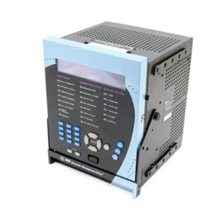
SR469-P5-HI-A20-H, as the high-end model of GE SR469 series relays, is positioned to provide a dual guarantee of "preventive protection+precise fault removal" for medium and high voltage motors with high rated voltage, high power, and complex operating conditions. Its design philosophy is centered around "reliability first, intelligent control", and compared to traditional relays, it has the following outstanding advantages:
-Full condition adaptation: Multiple sets of protection logic are preset for the entire process of motor starting, steady-state operation, load fluctuation, shutdown, etc., which can adapt to different types of medium and high voltage motors such as asynchronous motors and synchronous motors.
-High precision detection: Using a 16 bit high-precision AD sampling chip, the acquisition accuracy of motor current, voltage, temperature and other parameters reaches ± 0.2%, ensuring the accuracy of fault diagnosis.
GE SR469-P5-HI-A20-H motor protection relay
Product core positioning and design advantages
SR469-P5-HI-A20-H, as the high-end model of GE SR469 series relays, is positioned to provide a dual guarantee of "preventive protection+precise fault removal" for medium and high voltage motors with high rated voltage, high power, and complex operating conditions. Its design philosophy is centered around "reliability first, intelligent control", and compared to traditional relays, it has the following outstanding advantages:
-Full condition adaptation: Multiple sets of protection logic are preset for the entire process of motor starting, steady-state operation, load fluctuation, shutdown, etc., which can adapt to different types of medium and high voltage motors such as asynchronous motors and synchronous motors.
-High precision detection: Using a 16 bit high-precision AD sampling chip, the acquisition accuracy of motor current, voltage, temperature and other parameters reaches ± 0.2%, ensuring the accuracy of fault diagnosis.
-Strong anti-interference ability: certified by EMC (electromagnetic compatibility) level, with built-in multi-stage filtering circuit and isolation design, it can resist strong electromagnetic interference, voltage fluctuations and other interference factors in industrial sites.
-Intelligent integration: supports seamless integration with control systems such as PLC and DCS, enabling remote monitoring of motor operation data and centralized configuration of protection parameters.
Core protection function and monitoring function
The functions of SR469-P5-HI-A20-H cover three core areas: motor protection, operation monitoring, and fault diagnosis, which can be further divided into the following categories:
1. Comprehensive fault protection function
This relay has more than 20 built-in protection logics, which can accurately identify various fault risks during motor operation, trigger protection actions in a timely manner (such as tripping and alarm), and avoid the expansion of faults. The core protection functions include:
-Overcurrent protection: divided into locked rotor protection (overcurrent during start-up), overload protection (overcurrent during steady-state operation), and short-circuit protection (severe overcurrent). The protection threshold and delay time can be customized according to the rated current and start-up characteristics of the motor to avoid misoperation during start-up.
-Voltage abnormality protection: covering overvoltage, undervoltage, and voltage imbalance (phase failure, reverse phase sequence) protection. When the grid voltage fluctuates or wiring errors occur, the motor power supply is quickly cut off to prevent winding insulation damage.
-Temperature protection: Supports the integration of motor winding embedded temperature sensors (such as PT100, K-type thermocouples) and bearing temperature sensors to achieve real-time monitoring of the motor body temperature. When the temperature exceeds the safety threshold, protection is triggered.
-Special working condition protection: including ground fault protection (through zero sequence current detection), locked rotor protection (for rotor jamming scenarios during startup), underload protection (to prevent energy waste and equipment loss caused by motor idling), etc.
2. Real time operation monitoring and data collection
Relays have powerful parameter acquisition and real-time monitoring capabilities, which can continuously collect key operating data of motors and output it through local display panels or remote communication interfaces, providing comprehensive equipment status information for operation and maintenance personnel:
-Electrical parameters: three-phase current, three-phase voltage, power factor, active power, reactive power, cumulative electricity, etc. The collection period can be as short as 10ms to ensure real-time data.
-Temperature parameters: motor winding temperature, front and rear bearing temperature, supporting up to 8 temperature signal connections.
-State parameters: motor operating status (running/stopping/fault), protection action status, relay working status (power supply, communication), etc.
3. Fault diagnosis and data recording
For the convenience of fault tracing and equipment maintenance, the relay is equipped with a large capacity data storage unit, which has complete fault diagnosis and recording functions:
-Fault record: It can store the latest 100 fault information, each record containing the fault type, occurrence time, and current/voltage/temperature parameters at the time of the fault, providing accurate basis for fault location.
-Event recording: Record key events such as motor start, stop, protection actions, parameter modifications, etc., with timestamp accuracy of milliseconds.
-Self check function: Regularly perform self checks on the sampling circuit, output circuit, and communication module of the relay itself. When a fault occurs, it will promptly sound an alarm to avoid protection failure.
4. Flexible control and communication functions
Relays support multiple control modes and communication protocols, seamlessly integrating into industrial automation control systems
-Control mode: Supports local manual control (via panel buttons) and remote automatic control (via PLC/DCS commands), enabling coordinated control of multiple starting modes such as direct motor start, star delta start, and soft start.
-Communication Protocol: Built in mainstream industrial communication protocols such as EtherNet/IP, Modbus TCP, PROFINET, etc., with a communication speed of up to 100Mbps, it can achieve remote configuration of protection parameters, real-time uploading of operating data, and remote fault reset.
Key technical parameters
power input
AC/DC 85-265V, Power consumption ≤ 15VA, equipped with overvoltage and overcurrent protection
Applicable motor specifications
Voltage level: 3kV-15kV; Power range: 100kW-10MW; Suitable motor type: asynchronous/synchronous motor
Current input
Connected through a current transformer, rated input: 5A (secondary side), measurement range: 0.1A-20A
Voltage input
Connected through a voltage transformer, rated input: 100V (secondary side), measurement range: 0-120V
Temperature input
Supports PT100 (-50 ℃ -200 ℃), K-type thermocouple (0 ℃ -400 ℃), up to 8 inputs
Protecting Action Accuracy
Current protection accuracy ± 0.2%, voltage protection accuracy ± 0.2%, temperature protection accuracy ± 1 ℃
output circuit
8-way relay output (normally open/normally closed optional), contact capacity: AC 250V/5A, DC 24V/10A
communication interface
2 RJ45 Ethernet ports, supporting EtherNet/IP, Modbus TCP, PROFINET
working environment
Temperature: -20 ℃ -70 ℃; Humidity: 5% -95% (no condensation); Protection level: IP20 (panel)
mechanical properties
Installation method: panel type/drawer type; Weight: Approximately 1.2kg
Applicable scenarios and typical applications
With its high reliability, comprehensive protection functions, and flexible adaptability, SR469-P5-HI-A20-H is widely used for the protection of medium and high voltage motors in various industrial scenarios, with typical applications including:
1. Power industry: Used for the protection of key auxiliary motors such as induced draft fans, supply fans, and feed pumps in thermal power plants and hydropower stations. Once these motors fail, they will directly affect the power generation efficiency of the unit. The fast protection capability of relays can reduce downtime caused by faults.
2. Petrochemical industry: Suitable for compressors and pump motors in refineries and chemical plants. In flammable and explosive industrial environments, the stable operation of relays can avoid safety accidents caused by motor failures, while supporting remote monitoring and reducing the workload of on-site operation and maintenance personnel.
3. Steel metallurgy industry: used for protecting heavy-duty motors such as blast furnace blowers, converter tilting motors, and rolling mill motors. These motors have large load fluctuations, and the overload protection and locked rotor protection functions of relays can effectively cope with impact loads and prevent motor damage.
4. Mining and building materials industry: used for motor protection in mining elevators, crushers, cement rotary kilns, etc. In environments with high dust and frequent voltage fluctuations, the anti-interference design and wide voltage input characteristics of relays can ensure the reliable implementation of protection functions.
5. Municipal engineering: Used for aeration fans, sewage pump motors, and underload protection of relays in sewage treatment plants to detect pump body idling problems in a timely manner. Temperature protection can prevent motor damage due to long-term overheating, ensuring continuous operation of the sewage treatment system.
Key points for installation, debugging, and operation and maintenance
To ensure the optimal performance of SR469-P5-HI-A20-H relay, it is necessary to strictly follow the installation and commissioning specifications, and establish a sound operation and maintenance mechanism. The specific points are as follows:
1. Installation specifications
-The installation location should be far away from strong magnetic field equipment (such as large transformers and contactors) to avoid electromagnetic interference affecting sampling accuracy; At the same time, ensure good ventilation, stay away from heat sources and humid environments, and meet temperature and humidity requirements.
-The wiring of current transformers (CT) and voltage transformers (VT) must strictly distinguish between phases to ensure phase consistency of three-phase current and voltage, and avoid protection logic disorder caused by wiring errors.
-The power and signal lines of the relay need to be laid separately, using shielded cables to transmit temperature and communication signals. The shielding layer should be grounded at one end to reduce interference.
2. Key debugging points
-Before configuring parameters, it is necessary to clarify the rated parameters of the motor (rated power, rated voltage, rated current, starting mode), and set protection thresholds based on the characteristics of the motor (such as the inverse time curve of overload protection and the delay time of locked rotor protection).
-Conduct simulated fault testing: Simulate overcurrent, overvoltage, and phase failure scenarios using specialized testing equipment to verify the accuracy and timeliness of relay protection actions, ensuring that the protection logic matches the on-site requirements.
-Communication debugging: Configure communication parameters (IP address, port number, protocol type), establish a connection with the PLC/DCS system, test the execution of data upload and remote control instructions to ensure stable communication.
3. Daily operation and troubleshooting
-Daily inspection: Regularly check whether the relay panel display is normal and whether the alarm indicator light is on; Check whether the wiring terminals are loose or overheating, and whether the insulation layer of the cable is damaged; Clean the dust on the panel and heat dissipation holes to ensure good heat dissipation.
-Data monitoring: Regularly check the motor operation data through the upper computer system, compare historical data, analyze the trend of changes in parameters such as current and temperature, and identify potential fault risks in advance (such as the gradual increase of current may indicate insulation aging of the motor winding).
-Fault handling: When the relay triggers the protection action, first check the panel fault code or upper computer fault record, and investigate the cause according to the fault type (such as overcurrent fault, check whether the load is too large, whether the motor is stuck; high temperature, check whether the cooling system is normal). After troubleshooting, the motor can only be restarted by resetting the relay through the panel or remote control.
-Regular calibration: It is recommended to calibrate the accuracy of the relay once a year, by inputting analog current and voltage signals through a standard signal source to verify whether the sampling accuracy and protection action threshold meet the requirements, ensuring the accuracy of the protection function.
- User name Member Level Quantity Specification Purchase Date
- Satisfaction :
-


