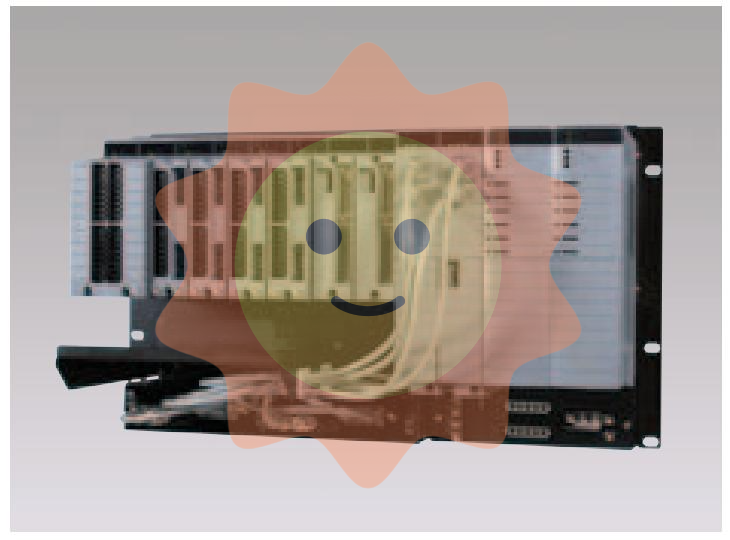
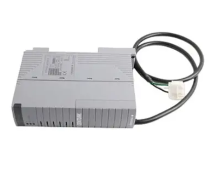
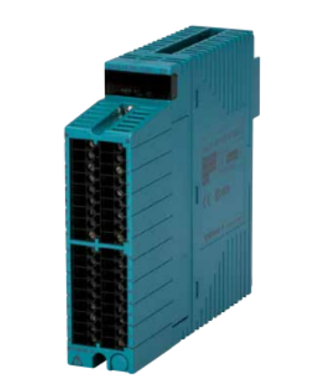
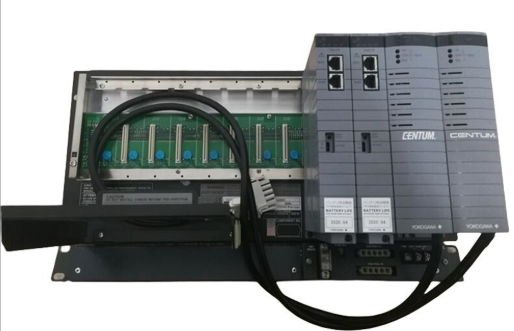
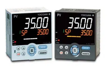
In the generator system, SR489-P1-HI-A20-E plays a dual core role: on the one hand, as a "safety guard", it accurately collects key parameters such as voltage, current, frequency, and temperature of the generator, monitors various abnormal working conditions (such as overvoltage, overcurrent, short circuit, overload, etc.) in real time, and quickly triggers protective actions (such as cutting off excitation, tripping and stopping) when faults occur, minimizing equipment damage; On the other hand, as the "control center", it realizes the functions of generator start stop control, excitation regulation, parallel operation synchronization, etc., and supports bidirectional communication with the upper computer system, providing comprehensive operation data and remote control capabilities for operation and maintenance personnel.
GE SR489-P1-HI-A20-E Generator Management Relay
Product positioning: The "safety guard" and "control center" of the generator
In the generator system, SR489-P1-HI-A20-E plays a dual core role: on the one hand, as a "safety guard", it accurately collects key parameters such as voltage, current, frequency, and temperature of the generator, monitors various abnormal working conditions (such as overvoltage, overcurrent, short circuit, overload, etc.) in real time, and quickly triggers protective actions (such as cutting off excitation, tripping and stopping) when faults occur, minimizing equipment damage; On the other hand, as the "control center", it realizes the functions of generator start stop control, excitation regulation, parallel operation synchronization, etc., and supports bidirectional communication with the upper computer system, providing comprehensive operation data and remote control capabilities for operation and maintenance personnel.
Compared to traditional discrete protection devices, this relay adopts a highly integrated design, which not only simplifies the wiring and structure of the generator control system, but also improves the reliability and response speed of the system. It is the core equipment of modern generator automation control.
Core function: Multi dimensional support and intelligent control
1. Comprehensive protection function, building a strong security defense line
SR489-P1-HI-A20-E has a protection function that covers the entire operating cycle of the generator, and can accurately trigger graded protection actions according to different fault types, including:
-Electrical quantity protection: overvoltage protection (with adjustable action threshold and delay), undervoltage protection (to avoid the impact of low voltage on the load and generator), overcurrent protection (with time limit and inverse time limit characteristics, suitable for different short-circuit scenarios), short-circuit protection (quick break action, quick cut-off of fault circuit), frequency anomaly protection (over frequency/under frequency, to deal with abnormal speed problems), reverse power protection (to prevent the generator from reversing power to the grid and avoid equipment damage caused by reverse).
-Non electrical quantity protection: Generator winding temperature protection, bearing temperature protection, lubricating oil temperature protection, cooling water temperature protection, etc. are achieved through external sensors. When the temperature exceeds the set range, an alarm signal is first issued. If the abnormality persists, the shutdown protection is triggered.
-Special protection: excitation fault protection (monitoring abnormal excitation circuit, such as demagnetization and excitation overcurrent), zero sequence current protection (used to detect single-phase grounding faults), covering the core risk points of generator operation in all aspects.
2. High precision monitoring function, real-time monitoring of operating status
The relay is equipped with a high-precision data acquisition module, which supports real-time monitoring of the electrical and non electrical parameters of the generator, with a monitoring accuracy of 0.2 level. Key parameters include:
-Electrical parameters: three-phase voltage, three-phase current, power factor, active power, reactive power, apparent power, frequency, zero sequence voltage/current, etc. Real time calculation and display of power generation efficiency and energy consumption data.
-Non electrical parameters: Temperature, pressure, liquid level and other sensor signals are connected through analog input interfaces to achieve status monitoring of the generator body and auxiliary systems.
-Status parameters: generator operating status (running/shutdown/fault), protection action status, relay working status (power supply, communication), etc. All monitoring data can be visually viewed through panel indicator lights or upper computer system.
3. Flexible control function, adapted to diverse operational needs
This relay supports multiple control modes and can be flexibly configured according to application scenarios. The core control functions include:
-Start stop control: Supports manual and automatic start stop modes. In automatic mode, the generator can be triggered to start by external signals (such as power outage signals or upper computer commands) to meet the fast response requirements of the backup power supply.
-Excitation regulation: Built in excitation regulation module can accurately control the excitation current of the generator through PID algorithm, ensuring stable output voltage and adapting to load fluctuation scenarios (such as sudden changes in industrial loads).
-Parallel operation control: It has the function of quasi synchronous parallel operation. By monitoring the voltage, frequency, and phase difference between the generator and the grid, it automatically adjusts the generator parameters to achieve smooth parallel operation. It is suitable for scenarios where multiple generators operate in parallel or are connected to the grid.
-Load transfer and distribution: During parallel operation, the active and reactive power of each generator can be automatically balanced and distributed to avoid overloading of a single device and improve system efficiency.
4. Efficient communication and data management functions
SR489-P1-HI-A20-E is equipped with rich communication interfaces and supports multiple industrial communication protocols, achieving seamless integration with upper computer systems and SCADA systems:
-Communication interface: RS485 and Ethernet interfaces are standard, and some models support CANopen interfaces to meet different communication distance and speed requirements.
-Supporting protocols: Compatible with mainstream protocols such as Modbus RTU, Modbus TCP, IEC 61850, etc., it can quickly integrate into existing automation systems.
-Data Management: Equipped with historical data recording function, it can store fault information and operating parameter curves (such as voltage and current change trends), with a storage capacity of over 100000 records, and data retention time can be set; Support fault code query for quick location and maintenance.
5. Humanized operation and display function
The relay is equipped with a large-sized LCD display screen that supports multiple languages such as Chinese and English, and can refresh key operating parameters and status information in real time; The panel is equipped with physical operation buttons, which facilitate on-site personnel to set parameters, switch modes, and reset faults. At the same time, it supports remote parameter configuration and firmware upgrades through dedicated software such as GE Multilin Toolbox, improving operational convenience.
Key technical parameters: Quantitative performance indicators
The following are the core technical parameters of GE SR489-P1-HI-A20-E generator management relay, which accurately reflect its performance boundary and applicable conditions:
parameter category
technical indicators
Applicable generator types
Diesel generators, gas generators, steam turbine generators, etc., with a rated power range of 100kW-10MW
Input voltage range
Three phase AC 85V-265V (main power supply); DC 24V ± 10% (backup power supply, optional)
Voltage measurement range
0-690V AC (line voltage), accuracy ± 0.2%
Current measurement range
0-1000A (connected through current transformer, variable ratio configurable), accuracy ± 0.2%
Frequency measurement range
45Hz-65Hz, Accuracy ± 0.01Hz
Temperature measurement range
-40 ℃ -150 ℃ (connected through sensors such as PT100 and K-type thermocouple), with an accuracy of ± 0.5 ℃
Protection action response time
≤ 10ms (short circuit protection); 10ms-10s (other protections, configurable)
Output contact capacity
AC 250V/5A, DC 30V/5A (relay output)
Communication speed
RS485:9600-115200bps; Ethernet: 10/100Mbps
Working environment temperature
-20℃-70℃
relative humidity
5% -95% (no condensation)
Protection level
IP20 (panel), IP40 (body, installed inside the cabinet)
Applicable scenarios: covering diverse power generation needs
With comprehensive functionality and stable performance, SR489-P1-HI-A20-E is widely used in various generator control systems, with core applicable scenarios including:
1. Industrial self owned power station
In the self owned power stations of large industrial enterprises such as steel, chemical, and cement, this relay can achieve comprehensive protection and precise control of the generator, ensuring that the generator can quickly start and provide stable power supply in the event of power outages or fluctuations in the power grid, avoiding losses caused by production interruptions. At the same time, its parallel operation control function supports the collaborative work of multiple generators to meet the high load electricity demand of enterprises.
2. Backup power system
In places such as data centers, hospitals, banks, and communication base stations that require extremely high reliability of power supply, SR489-P1-HI-A20-E serves as the core control equipment for backup generators, which can achieve seamless switching (switching time ≤ 10 seconds) between "power grid failure generator automatic start stable power supply", ensuring the continuous operation of critical loads. Its high-precision voltage regulation function ensures stable output voltage and avoids impact on sensitive equipment such as servers and medical devices.
3. Distributed energy stations
In distributed energy stations supporting photovoltaic and wind power, this relay can achieve coordinated operation between the generator and the new energy generation system, and improve energy utilization efficiency through precise power allocation and grid control. At the same time, its comprehensive protection function can cope with the impact of fluctuations in new energy generation and ensure the stable operation of the system.
4. Mobile power generation equipment
In mobile power generation vehicles used in emergency rescue and field operations, SR489-P1-HI-A20-E, with its compact structure and excellent anti vibration performance (compliant with IEC 60068-2-6 standard), can adapt to complex mobile environments, achieve reliable protection and control of mobile generators, and provide stable emergency power supply for the site.
Application precautions: Ensure stable operation
1. Installation specifications
Relays should be installed in control cabinets with good ventilation, no dust, no corrosive gases, and no strong electromagnetic interference, avoiding direct sunlight and rainwater erosion. The installation position should be far away from heating elements (such as contactors and frequency converters), and the distance from other equipment should not be less than 15cm to ensure good heat dissipation. When wiring, it is necessary to strictly distinguish between the power circuit, signal input circuit, and output circuit to avoid equipment damage caused by wiring errors.
2. Parameter configuration
During on-site debugging, it is necessary to accurately configure the protection threshold (such as overvoltage action value set to 110% -120% of the rated voltage), control parameters (such as excitation regulation PID parameters), and communication parameters based on the rated parameters of the generator (such as rated voltage, rated current, rated power), load characteristics, and operating requirements. It is recommended to use GE specialized debugging software for parameter configuration. After configuration, simulation fault testing should be conducted to verify the accuracy of protection actions.
3. Daily maintenance
Regularly (monthly) check the status of the relay panel indicator lights to confirm that the power, communication, and operational status are normal; Clean the equipment surface and wiring terminals once a quarter, remove dust and oxide layers, and avoid poor contact; Conduct a comprehensive verification once a year, including parameter accuracy, protection action response time, communication stability, etc., to ensure that the equipment performance meets the requirements.
4. Fault handling
When a relay issues a fault alarm, the fault code should be queried through the panel display screen or upper computer system first, and the problem type should be located based on the fault code: if it is "parameter abnormality", the parameters can be reconfigured; If it is a 'sensor malfunction', the sensor wiring and performance need to be checked; If it is an internal fault of the relay, please contact GE's official after-sales personnel in a timely manner to avoid disassembling and repairing it yourself.

- User name Member Level Quantity Specification Purchase Date
- Satisfaction :
-


