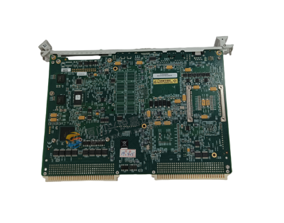
-Main model: GE V7768-320000
-Complete code: 3509301007768-320000A0
-Manufacturer: General Electric (GE) Industrial Automation Division
-Product category: Industrial grade controller core module, commonly used as the core control unit in process control, intelligent manufacturing, and automation systems
GE V7768-320000 3509301007768-320000A0 Controller Module
Basic information of module
1. Core model identification
-Main model: GE V7768-320000
-Complete code: 3509301007768-320000A0
-Manufacturer: General Electric (GE) Industrial Automation Division
-Product category: Industrial grade controller core module, commonly used as the core control unit in process control, intelligent manufacturing, and automation systems
2. Applicable scenarios
This module is widely used in industrial fields such as power, petrochemicals, metallurgy, intelligent manufacturing, and rail transit, which require extremely high control accuracy and system stability. It can be used as the core processing module of distributed control systems (DCS) and programmable logic controllers (PLC) systems to achieve real-time monitoring and precise control of complex industrial processes.
Core functions and performance parameters
1. Core processing capability
-Processor architecture: Adopting GE's dedicated high-performance industrial processor, it has the ability of multitasking parallel processing, and can simultaneously run multiple tasks such as control algorithms, data acquisition, communication interaction, etc
-Computing speed: The instruction execution cycle can reach microsecond level, supporting fast computation of complex control logic (such as PID closed-loop control, fuzzy control, etc.) to meet high-frequency control requirements
-Memory configuration: Integrated large capacity high-speed RAM (random access memory) and non-volatile ROM (read-only memory) to ensure stable program storage and high-speed data exchange. ROM supports program solidification to prevent program loss caused by unexpected power outages
2. Input/output (I/O) characteristics
The module supports the access and output of multiple types of I/O signals, with good compatibility and scalability, including:
-Analog signal: supports the acquisition and output of 4-20mA current signal and 0-10V voltage signal, with an accuracy of ± 0.1%, suitable for monitoring and control of continuous parameters such as temperature, pressure, and flow rate
-Digital signal: Supports DI (digital input) and DO (digital output) signals, adopts optoelectronic isolation technology, has strong anti-interference ability, can directly drive external devices such as relays and indicator lights, and input/output response time ≤ 1ms
-I/O expansion capability: GE series I/O expansion modules can be connected through dedicated bus interfaces, supporting expansion of up to hundreds of I/O points to meet the needs of systems of different scales
3. Communication function
Having rich communication interfaces and protocol support, ensuring efficient interconnection with other devices within the system:
-Interface type: Standard Ethernet (RJ45), RS485, RS232 and other interfaces, some versions support industrial Ethernet protocols such as PROFINET, Modbus TCP/RTU, EtherNet/IP, etc
-Communication speed: The maximum communication speed of the Ethernet interface can reach 100Mbps, and the RS485 interface supports an adjustable baud rate of 9600-115200bps to meet real-time data transmission requirements
-Networking capability: Supports multiple networking methods such as star and bus, seamlessly connects to industrial control networks, and enables bidirectional data exchange with upper computers, touch screens, and other controllers
4. Reliability and environmental adaptability
-Power supply requirements: Supports wide voltage input of DC 24V or AC 220V, with overvoltage, overcurrent, and short circuit protection functions, and can still work stably within a power supply fluctuation range of ± 10%
-Working environment: The working temperature range is -20 ℃~60 ℃, with a relative humidity of 10%~90% (no condensation), suitable for harsh industrial environments
-Anti interference performance: Complies with the IEC 61000-4 series electromagnetic compatibility standards, has strong anti electromagnetic interference (EMI) and electromagnetic radiation (EMC) capabilities, and can operate stably in strong electromagnetic environments
-MTBF (Mean Time Between Failures): ≥ 100000 hours, ensuring long-term stable operation of the system and reducing maintenance costs
Key points for installation and debugging
1. Installation specifications
-Installation method: Standard DIN rail or screw fixed installation is used, and the installation position should be far away from strong magnetic fields, high temperature heat sources, and vibration sources to ensure good heat dissipation of the module
-Wiring requirements: Strictly follow the module terminal diagram for wiring. Analog and digital signal cables should be laid separately to avoid signal interference; After the wiring is completed, it is necessary to tighten the terminal screws to prevent poor contact
2. Debugging process
1. Pre power on inspection: Confirm that the power supply voltage and wiring method meet the module requirements, and that the interface connection is secure
2. Initialization configuration: Connect the module through GE specialized programming software (such as GE Proficy Machine Edition) to complete basic configurations such as processor parameters, I/O address allocation, and communication protocols
3. Program download and testing: Download the written control program to the module for I/O signal testing and control logic verification to ensure that the module achieves control functions as expected
4. Online debugging: Connect the module to the entire control system for system integration debugging, verify the communication stability and data exchange accuracy with other devices
Maintenance and Precautions
-Regular maintenance: Conduct a comprehensive inspection of the module every 6 months, including cleaning the surface dust of the module, checking the tightness of the wiring terminals, testing the stability of the power supply voltage, etc
-Fault handling: If the module malfunctions, the power supply should be disconnected first, and the interface connection and wiring should be checked. If the problem cannot be solved, it can be repaired or replaced through GE's official after-sales service channel. It is prohibited to disassemble the module without authorization
-Software Upgrade: Regularly follow the official GE website, download and update module related programming software and firmware versions in a timely manner to obtain better performance and functional support
-Safety warning: Avoid touching the terminal parts during module operation to prevent electric shock; Before wiring or maintenance operations, the power supply must be disconnected to ensure safe operation

- User name Member Level Quantity Specification Purchase Date
- Satisfaction :
-


