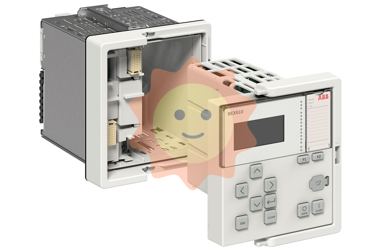
As a high-performance protection and control device, ABB REU615's panel design is closely focused on the convenience of operation and maintenance, the intuitiveness of information display, and the controllability of equipment status. This panel is the core carrier for user device interaction, and mastering its functional layout and operational logic is of great significance for improving equipment debugging efficiency and ensuring stable operation of the power system. This article will comprehensively analyze the ABB REU615 panel from four dimensions: basic panel composition, core functional areas, operation methods, and precautions.
ABB REU615 panel
As a high-performance protection and control device, ABB REU615's panel design is closely focused on the convenience of operation and maintenance, the intuitiveness of information display, and the controllability of equipment status. This panel is the core carrier for user device interaction, and mastering its functional layout and operational logic is of great significance for improving equipment debugging efficiency and ensuring stable operation of the power system. This article will comprehensively analyze the ABB REU615 panel from four dimensions: basic panel composition, core functional areas, operation methods, and precautions.
Basic positioning and design concept of panel
ABB REU615 is mainly used for protection, control, and monitoring of medium and low voltage power systems. Its panel design follows the principle of "people-oriented", taking into account the operating habits of professional operation and maintenance personnel and the timeliness of on-site emergency response. The panel adopts a modular layout, clearly dividing the display area, operation area, and status indication area. At the same time, it has a dust-proof and anti misoperation structural design, which can adapt to complex industrial environments such as power distribution rooms and substations.
The overall panel is made of high-strength engineering plastic material, with a scratch resistant surface treatment. The key operation buttons are designed with protrusions and clear markings, making it easy for operators to quickly locate and operate in low light or when wearing insulated gloves.
2、 Detailed explanation of the core functional areas of the panel
The ABB REU615 panel can be divided into three core parts according to function: display area, operation button area, and status indicator area. Each area works together to achieve comprehensive presentation and precise control of equipment information.
1. Display area: the core carrier of information presentation
The display area adopts a high-resolution monochrome or color LCD display screen, usually 3.5 inches or 4.3 inches in size, with the characteristics of wide viewing angle and high contrast, which can display content clearly in strong or low light environments. The display screen mainly presents the following information:
-Operation status information: including the current operation mode of the device (normal, debugging, fault), system time, real-time voltage/current values, power factor and other key electrical parameters. Some parameters support real-time curve display, making it easy for operators to intuitively grasp the operation status of the power grid.
-Protection event information: When the system experiences faults such as overcurrent, overvoltage, short circuit, etc., the display screen will immediately pop up detailed information such as fault type, occurrence time, fault parameters, etc., and support historical event query, providing a basis for fault troubleshooting.
-Setting menu interface: After entering the setting menu through the operation keys, the display screen will present the device parameter configuration interface, including protection setting, communication parameter configuration, logic function selection, etc. During the parameter setting process, there will be clear input prompts and verification feedback.
-Alarm message: When the device itself experiences hardware failures (such as power supply abnormalities, communication interruptions) or detects abnormal trends in the power grid, an alarm prompt will be displayed, and some severe alarms will be accompanied by sound and light alarms.
2. Operation button area: a key interface for precise control
The operation button area is located below or on the side of the display screen, and can be divided into function shortcut keys, navigation keys, confirm/cancel keys, and numeric input keys according to functions. Some models are also equipped with custom buttons to meet personalized operation needs. The functions of each button are as follows:
Key type
Specific buttons
core functionality
Function shortcut keys
Run, Settings, Events, Reset
One click access to the corresponding function interface, the "reset" button can clear the current alarm or fault state (must meet the reset conditions)
Navigation buttons
Up, down, left, and right directional keys
Used for menu navigation, parameter selection, and cursor movement, it can control the timeline zoom when viewing curves
Confirm/Cancel button
Confirm "" Cancel "
Confirm the current operation or exit the current interface. When setting parameters, press the "confirm" button to trigger parameter save verification
Digital input button
0-9 numeric keys, decimal point keys
Used to protect inputs of numerical parameters such as fixed values and communication addresses, supporting unit switching (such as A/kA, V/kV)
Custom Key
F1 "" F2 "(configurable)
It can be configured as a shortcut key for commonly used functions through software, such as "emergency disconnection" and "constant value switching"
3. Status indication area: intuitive feedback of equipment operation status
The status indication area consists of multiple LED indicator lights, which are usually distinguished by different colors to indicate the type of status (red indicates fault/alarm, green indicates normal operation, yellow indicates standby/debugging). Some indicator lights have flashing functions to transmit more accurate information. The main indicator lights and their meanings are as follows:
-Power indicator light (PWR): Green constant light indicates that the device's power supply is normal; Not lit indicates a power failure; Flashing indicates that the power supply is in standby or transitional state.
-RUN indicator light: Green constant light indicates that the device is running normally; Flashing indicates that the device is in debugging mode or communication state; Not lit indicates that the device has not been started.
-Fault indicator light (FAULT): A constant red light indicates a serious fault (such as protective action or hardware damage) has occurred; Flashing indicates the presence of non emergency faults (such as abnormal parameters); Not lit indicates no malfunction.
-Alarm indicator light (ALM): Yellow constantly on or flashing indicates the presence of alarm information, and the specific type of alarm needs to be viewed in conjunction with the display screen.
-Communication indicator light (COM): Green flashing indicates normal communication (flashing frequency corresponds to communication rate); Not lit indicates communication interruption; Red flashing indicates communication abnormalities (such as data transmission errors).
-Protection action indicator light (TRIP): Red constant light indicates that the protection action has been exited; Flashing indicates that a protection action request has been issued but not yet executed; Not lit indicates no protective action.
Basic operation process of panel
Mastering the basic operation process of ABB REU615 panel can significantly improve equipment debugging and operation efficiency. The following is the standard procedure for common operations:
1. Equipment startup and status check
1. Connect the device power supply and observe whether the power indicator light (PWR) turns green and stays on. If it does not light up, check the power circuit.
2. Wait for the device self-test to complete (about 3-5 seconds), and the RUN indicator light will turn green and remain on, indicating that the device has entered normal operation.
3. Check the main interface of the display screen to confirm whether real-time parameters such as voltage and current are within the normal range and there are no abnormal alarm messages.
2. Protection setting
1. Press the "Settings" shortcut key to enter the main menu for parameter settings.
2. Select the "Protection Setting" option through the directional keys and press the "Confirm" button to enter the submenu.
3. Select the fixed value items that need to be set (such as overcurrent fixed value and speed determination value), and press the "confirm" button to enter the editing mode.
4. Enter the target value through the numeric keypad, press the "confirm" button, and the display screen will prompt "parameter saving". After completion, return to the previous menu.
5. After the settings are completed, press the "Run" shortcut key to return to the main interface and confirm that the set value settings have taken effect.
3. Fault event query
When the malfunction indicator light (FAULT) is on, press the "Event" shortcut key to enter the event query interface.
2. Use the directional keys to switch between the "Current Events" and "Historical Events" options, and view the time, type, and related parameters of the fault occurrence.
If you need to export event records, you can select the "Export" option in the "Event Menu" and upload the data to the backend system through the communication interface.
After completing the fault handling, press the "reset" button to clear the fault status, and the fault indicator light will turn off.
4. Device debugging mode operation
1. Press the "Settings"+"Confirm" combination key on the main interface (some models long press the "Debug" key), enter the debug password to enter the debug mode, and the run indicator light (RUN) will start flashing.
2. Logic function testing, output circuit verification, and other operations can be performed in the debugging menu. After the operation is completed, the device needs to exit the debugging mode and return to normal operation.
Precautions for panel operation
To ensure equipment safety and operational accuracy, the following precautions should be taken when using ABB REU615 panels:
-Permission management: Key operations such as parameter settings and debugging modes require the input of corresponding permission passwords. Unauthorized personnel are strictly prohibited from modifying core parameters. Passwords must be changed regularly and kept confidential.
-Operating environment: When operating the panel, it is necessary to ensure that there is no strong electromagnetic interference or dust or water mist on site. Operators should wear clean gloves to avoid fingerprints or stains affecting the sensitivity of the buttons and the clarity of the display screen.
-Emergency operation: In the event of a serious malfunction, if the panel operation cannot be controlled in a timely manner, the circuit should be immediately cut off through an external emergency disconnect device to prevent the malfunction from escalating.
-Parameter backup: Before modifying core configurations such as protection settings and communication parameters, the current parameters need to be saved through the "backup" function of the backend system or panel for quick recovery in case of operational errors.
-Daily maintenance: Regularly wipe the panel with a dry soft cloth to remove surface dust; Check whether the buttons are stuck or malfunctioning, whether the indicator lights are displaying normally, and promptly address any issues found.
- User name Member Level Quantity Specification Purchase Date
- Satisfaction :
-


