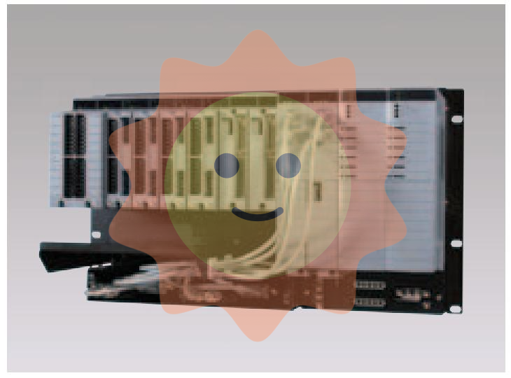
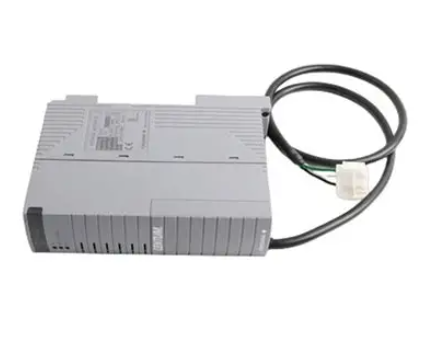
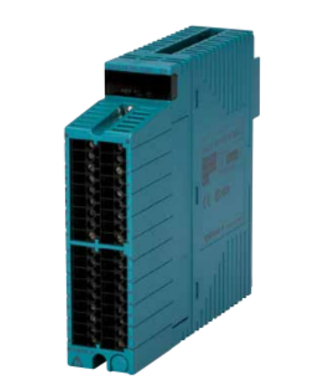
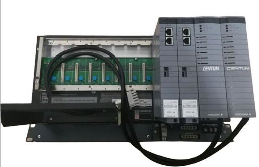
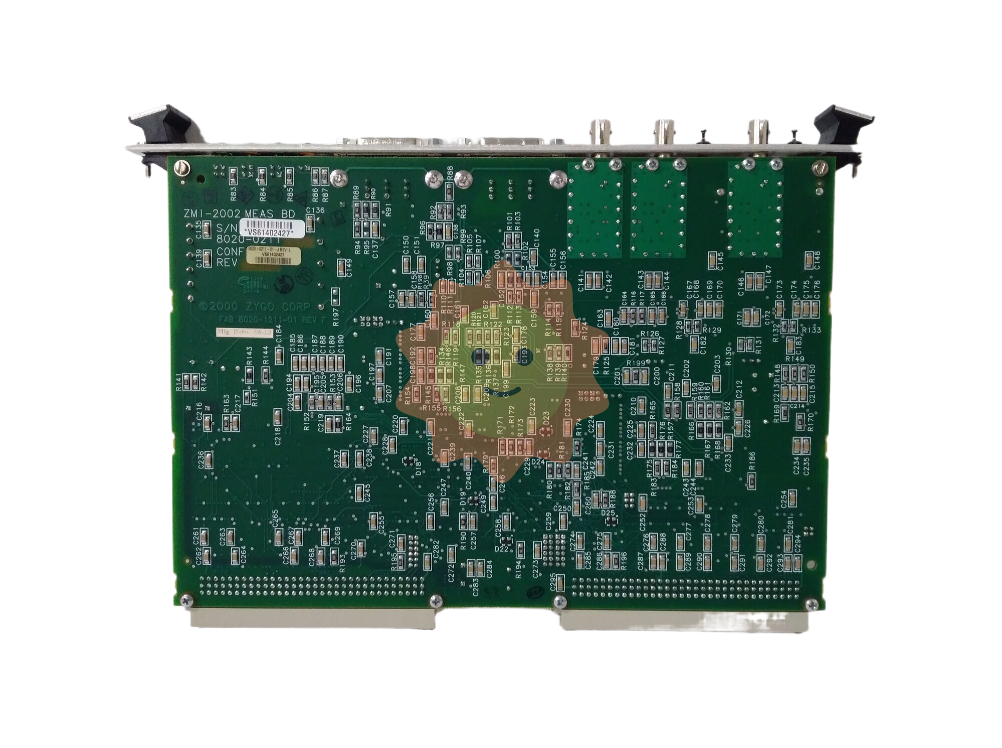
ZYGO ZMI-2002 8020-0211-1-J belongs to the ZMI-2000 series of dual axis laser measurement control boards. It is the core hardware launched by ZYGO, which integrates high-precision signal acquisition, real-time data processing, and laser parameter control. It is widely suitable for industrial laser processing and precision measurement scenarios.
ZYGO ZMI-2002 8020-0211-1-J Laser system measurement board card
Core positioning and key parameters of the product
ZYGO ZMI-2002 8020-0211-1-J belongs to the ZMI-2000 series of dual axis laser measurement control boards. It is the core hardware launched by ZYGO, which integrates high-precision signal acquisition, real-time data processing, and laser parameter control. It is widely suitable for industrial laser processing and precision measurement scenarios. The key parameters are as follows:
Measurement performance:
Number of measurement axes: Dual axis synchronous measurement
Resolution:<1 nm (nanometer level accuracy)
Measurement accuracy: ± 0.1 µ m (micrometer level error range)
Signal processing: Digital real-time processing, supporting high sampling rate signal capture
Physical specifications:
Size: 229 × 114 × 29 mm
Weight: 1.2 kg
Installation standard: Complies with VMEBus specification revised version C1, supports 6U size backplane installation
Environment and Protection:
Working temperature: 0 ° C to+40 ° C (requires constant temperature environment to ensure accuracy)
Protection level: IP54 (dustproof, waterproof, suitable for industrial workshop environment)
Stability: Low noise design, drift less than 0.05 µ m/h during long-term operation
Interface configuration:
Communication interface: P2 dedicated interface (simplified multi axis backplane slot requirements)
Programming interface: Supports VME/ISA bus interface, compatible with mainstream industrial control systems
Expansion interface: Reserve sensor and actuator control ports
Core functions and typical application scenarios
1. Core functions
Combining the dual attributes of measurement and control, its core functions can be divided into three modules:
High precision dual axis measurement:
Adopting advanced interferometric measurement technology, it synchronously collects displacement or position signals in two dimensions with a resolution of nanometer level, which can accurately capture micro size changes in laser processing. Paired with low-noise signal processing circuits, stable measurement accuracy can still be maintained in industrial environments.
Laser parameter programmable control:
Built in PLC control system, supporting user-defined programming, can accurately adjust key parameters such as laser power, processing speed, focus position, etc., adapting to different process requirements such as laser cutting, welding, marking, etc. Real time linkage between measurement data and control instructions is achieved through a high-speed data transmission channel (response delay<1ms).
System integration and security monitoring:
Support seamless integration with devices such as laser generators and motion platforms, monitor equipment operation status through built-in safety logic modules, and automatically trigger shutdown protection when measurement values exceed thresholds to ensure processing safety.
2. Typical application scenarios
Based on its high precision and programmable characteristics, it is mainly applied in the following fields:
Precision laser processing: wafer thickness monitoring in semiconductor chip laser cutting, and depth control in aerospace component laser welding.
High end manufacturing measurement: surface contour detection of optical components, micrometer scale size calibration of precision molds.
Industrial automation system: positioning error compensation for laser marking machines, real-time trajectory correction for 3D laser engraving.
Operation and maintenance standards
1. Installation and calibration
Installation requirements:
It needs to be fixed inside the shock absorber cabinet, away from strong electromagnetic interference sources (such as high-power motors); Connected through the VME bus backplane, the interface needs to be coated with conductive paste to ensure stable signal transmission; After installation, it is necessary to perform a grounding resistance test (with a requirement of<4 Ω).
Calibration process:
Environmental adaptation: After the card is electrified, it should be left to stand in the measurement environment for 30 minutes, and calibration should begin after the temperature stabilizes.
Benchmark calibration: Connect the standard calibration lens (known accuracy ± 0.01 µ m), execute the system self-test program, and automatically correct the measurement deviation.
Dual axis synchronous calibration: Adjust the sampling delay of both axes through dedicated software to ensure synchronization error<0.1 µ s
2. Daily maintenance and troubleshooting
Fault symptoms/possible causes/handling methods
Measurement data jump
Loose interface/electromagnetic interference
Re plug and tighten the P2 interface; Install electromagnetic shielding cover
Control command unresponsive
Bus communication failure/program error
Check the configuration of the VME bus; Rollback to a stable version of the program
Precision degradation exceeds the tolerance
Calibration expired/temperature fluctuation
Re execute benchmark calibration; Check if the ambient temperature exceeds the range of 0-40 ℃
The board indicator light is off
Power failure/internal short circuit
Measure input voltage (standard 24V DC); Replace the spare board for troubleshooting
3. Preventive measures
Regular maintenance: Clean the interface dust every month and perform comprehensive calibration every quarter (using ZYGO dedicated calibration tool);
Environmental control: Maintain a working environment temperature fluctuation of<± 2 ℃ and humidity of 40% -60%;
Spare parts management: Reserve vulnerable parts such as interface cables and cooling fans, and store boards in anti-static packaging.
- User name Member Level Quantity Specification Purchase Date
- Satisfaction :
-


