
Westinghouse DS/DSL series low-voltage power circuit breakers
Breaking capacity DS series 30000-65000A; DSL series 200000A DSL relies on built-in current limiting components to enhance breaking capacity, suitable for high short-circuit current scenarios
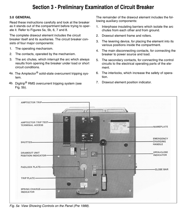
Amptector II-A (standard type) and Amptector I-A (with grounding protection) solid-state trip units with adjustable parameters, high repeatability, and no mechanical wear
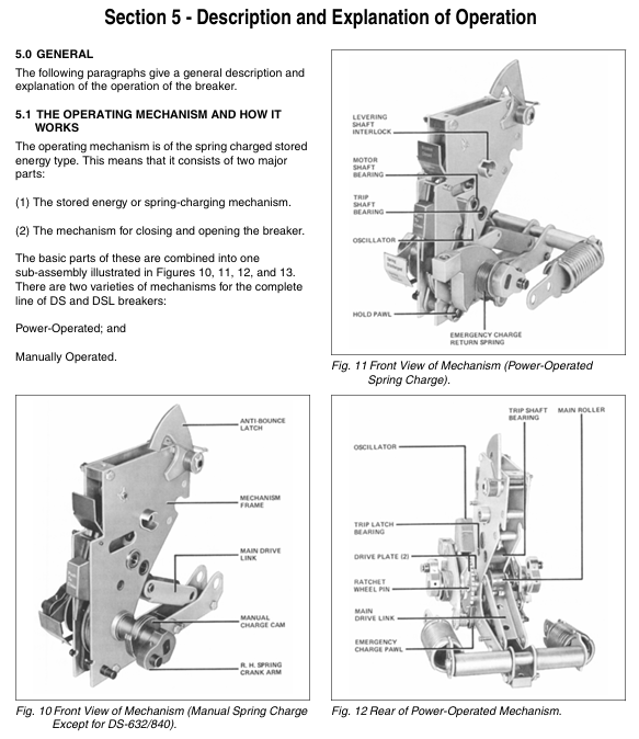
Operation modes: manual (spring energy storage), electric (motor energy storage+remote control). The electric type supports emergency manual energy storage to deal with control power failures
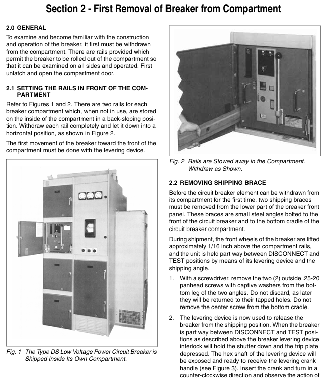
Installation forms include drawer style (mainstream) and fixed drawer style, which support four working positions for extraction, disconnection, testing, and connection, making maintenance convenient
Environmental adaptability operating temperature -20~+40 ℃, humidity ≤ 95% (no condensation). Keep away from dust and corrosive gases to avoid insulation aging
Westinghouse DS/DSL series low-voltage power circuit breakers
Detailed explanation of core product information
1. In depth analysis of technical parameters
Category parameter details note explanation
Voltage and current voltage range 208-600Vac, continuous current 50-4000A DSL series supports up to 600Vac, sensors can be replaced to adapt to different current levels
Breaking capacity DS series 30000-65000A; DSL series 200000A DSL relies on built-in current limiting components to enhance breaking capacity, suitable for high short-circuit current scenarios
Amptector II-A (standard type) and Amptector I-A (with grounding protection) solid-state trip units with adjustable parameters, high repeatability, and no mechanical wear
Operation modes: manual (spring energy storage), electric (motor energy storage+remote control). The electric type supports emergency manual energy storage to deal with control power failures
Installation forms include drawer style (mainstream) and fixed drawer style, which support four working positions for extraction, disconnection, testing, and connection, making maintenance convenient
Environmental adaptability operating temperature -20~+40 ℃, humidity ≤ 95% (no condensation). Keep away from dust and corrosive gases to avoid insulation aging
2. Product classification and core differences
(1) DS series (basic type)
Core features: No built-in current limiting components, simple structure, high cost-effectiveness, breaking capacity of 30000-65000A.
Mainstream models:
DS-206/206S: Frame current 800A, DS-206S is an upgraded version (with a breaking capacity of 42000A, better than DS-206's 30000A).
DS-416/416S/420: Frame current 1600A (416/416S), 2000A (420), 416S breaking capacity 65000A.
DS-632/840: Frame current 3200A (632), 4000A (840), suitable for large capacity distribution systems.
Applicable scenarios: Conventional industrial power distribution, commercial buildings, and situations with small fault currents (≤ 65000A).
(2) DSL series (current limiting enhanced type)
Core features: Equipped with a built-in current limiter, the breaking capacity has been increased to 200000A, which can quickly cut off large short-circuit currents and protect downstream equipment.
Mainstream models: DSL-206 (800A), DSL-416 (1600A), DSL-632/840 need to be used with an independent fuse car.
Applicable scenarios: Industrial scenarios with high short-circuit currents such as chemical and metallurgical industries, or critical distribution circuits that require enhanced protection.
(3) Fuse Trucks
Core features: Independent drawer design, equipped with Class L current limiting fuse, used in series with DS-632/840 circuit breaker.
Mainstream models: DS-3200 (3200A), DS-4000 (4000A), with fuse indicator.
Applicable scenario: Distribution systems that require graded protection, which achieve selective tripping through the combination of fuses and circuit breakers.
3. Function analysis of the trip unit
(1) Amptector II-A (Standard Type)
Adjustable parameters:
Long delay: Current 0.5-1.25 times the rated value of the sensor, time 8-36 seconds (at 6 times the rated current).
Short delay: current 4-10 x sensor rated value, time 0.18-0.5 seconds.
Instantaneous: current 4-12 times the rated value of the sensor, without delayed tripping.
Core function: Covering basic protection against overload and short circuit, supporting three combination modes: DU (long delay+instantaneous), SE (long delay+short delay), and TR (triple protection).
(2) Amptector I-A (optional)
Additional features: Added ground fault protection (adjustable current, delay of 0.22-0.5 seconds), trip indicator (overload/short circuit/ground fault indication separately).
Applicable scenarios: Ground fault sensitive scenarios (such as humid environments and places with high personal safety requirements).
Safety operation standards (including risk avoidance)
1. Personnel and Qualification Requirements
Operation qualification: Only personnel with low voltage distribution operation qualification are allowed to install and maintain, and they need to be familiar with equipment structure, interlocking mechanism, and electric shock risk.
Protective equipment: Insulated gloves and goggles must be worn during operation, insulated shoes must be worn, and slippers, bare feet, or loose clothing are prohibited (to avoid getting caught up in mechanical parts).
Prohibited behavior: Unauthorized personnel are prohibited from operating; It is prohibited to dismantle the arc extinguishing chamber and insulation barrier during equipment operation; Prohibit blocking or modifying interlocking devices (which may cause equipment misoperation and lead to accidents).
2. Installation and wiring safety
Pre installation inspection:
Check the nameplate parameters (voltage, current, breaking capacity) to match the system, and confirm that the circuit breaker is not damaged during transportation (contacts, arc extinguishing chamber, interlocking components are intact).
The drawer type circuit breaker needs to check that the guide rail and rocker are not deformed, and that the energy storage spring is not fatigued or corroded.
Wiring specifications:
Main circuit wiring: The tightening torque meets the requirements (copper bars/cables need to be crimped to the terminals) to avoid loosening and heating; The cross-sectional area of the three-phase wires is consistent, and the phase correspondence is correct.
Control circuit wiring: The electric operation type needs to be connected to a compliant control power supply (AC120/240V or DC48/125/250V), and the connection between the trip unit and the actuator should be firm with correct polarity (otherwise the protection function will fail).
Grounding requirements: The circuit breaker frame must be reliably grounded with a grounding resistance of ≤ 4 Ω to avoid electric shock caused by leakage.
3. Operation and operational safety
Working position operation:
Remove position: only used for maintenance or replacement. The energy storage spring must be released first, and all power sources must be disconnected. It is forbidden to remove it while it is still live.
Disconnect position: Both the main and auxiliary contacts are disconnected, which can be locked to prevent misoperation and is used for isolation and maintenance.
Test position (TEST): The auxiliary contact is connected, which can test the closing/tripping action and tripping function. The main circuit is not powered.
CONNECT: Normal operating position, it is necessary to confirm that the mechanical stop is in place, the interlocking device is locked, and it is prohibited to switch positions in the closed state.
Energy storage and closing operation:
Manual energy storage: DS-206 and other models require a single stroke downward pull on the energy storage handle, while DS-416 and above require multiple presses on the ratchet wheel. After energy storage is completed, there will be a "click" sound and the spring energy storage indicator light will light up.
Electric energy storage: After connecting to the control power supply, the circuit breaker will automatically store energy in the test/connection position. In case of energy storage failure, emergency manual energy storage can be used.
Closing taboos: Do not close with load; Do not repeatedly close the circuit when the short circuit fault has not been resolved; Do not close the circuit with current exceeding the nameplate.
Fault handling safety:
Troubleshooting after tripping: Overload tripping requires reducing the load, short-circuit tripping requires troubleshooting for line faults, grounding faults require checking the grounding circuit, and DSL series requires confirming whether the current limiting element is blown.
Emergency stop: In the event of a serious malfunction, emergency stop can be achieved through the panel trip button or remote trip signal, and forced locking and closing are prohibited.
4. Environment and Protection Safety
Operating environment: It is necessary to maintain dryness, cleanliness, good ventilation, avoid dust, oil mist, corrosive gases (such as chlorine and ammonia), and prevent contact oxidation and insulation aging.
Temperature control: When the ambient temperature exceeds 40 ℃, it is necessary to reduce the capacity (reduce the capacity by 10% for every 10 ℃ increase), and avoid direct sunlight or proximity to heat sources.
Moisture prevention measures: Insulation inspection should be strengthened in humid environments, and insulation resistance should be measured regularly (main circuit ≥ 1M Ω, control circuit ≥ 2M Ω).
Complete operation process (installation → debugging → maintenance)
1. Installation process (drawer style as an example)
Guide rail preparation: Open the circuit breaker cabinet door, unfold the built-in guide rail to a horizontal position, and ensure that the guide rail is not deformed or stuck.
Remove transportation fixing: Remove the transportation bracket and plastic protective cover on the circuit breaker, and check that the energy storage spring is not preloaded (released during transportation).
Push in the circuit breaker: Align the circuit breaker with the guide rail, slowly push it into the extraction position, insert the joystick and rotate it clockwise to switch to the disconnection position, test position, and connection position in sequence. Each position needs to be confirmed to be mechanically locked in place (with a "click" sound).
Wiring operation:
Main circuit: Connect the incoming and outgoing copper bars according to the phase, tighten the bolts (refer to the equipment manual for torque), and check the balance of the three-phase resistance.
Control circuit: Connect control power supply, remote closing/tripping signal, tripping unit power supply, check wiring diagram to avoid reverse polarity connection.
Grounding: Connect the grounding terminal of the circuit breaker frame reliably to the cabinet grounding bar.
Insulation test: Use a 500V megohmmeter to measure the insulation resistance of the main circuit. A resistance of ≥ 1M Ω is considered qualified, otherwise moisture or wiring faults need to be investigated.
2. Debugging process
Energy storage testing:
Manual energy storage: Operate the energy storage handle, confirm that the energy storage is completed, and the spring energy storage indicator light will turn on, and the closing mechanism can operate normally.
Electric energy storage: Connect the control power supply, the circuit breaker automatically stores energy, observe that the energy storage motor runs normally, and the energy storage time is ≤ 30 seconds.
Closing/tripping test (test position):
Manual closing: Press the closing button to close the circuit breaker, the closing indicator light will light up, and the contacts will be closed in place; Press the trip button, the circuit breaker trips, the trip indicator light lights up, and the action is smooth without any jamming.
Electric closing/tripping: Through remote control signal testing, confirm that the action response is timely (≤ 0.5 seconds) and there is no misoperation.
Release unit test:
Long delay test: Use a dedicated testing kit to input 1.25 times the rated current of the sensor and verify that the trip time meets the set value (8-36 seconds).
Short delay test: Input 6 times the rated current of the sensor and verify the trip time of 0.18-0.5 seconds.
Instantaneous test: Input 10 times the rated current of the sensor to verify instantaneous tripping.
Grounding fault test (I-A type): Input the set grounding current, verify the delayed tripping and indicator action.
Interlocking function test:
Attempt to switch to the open position while in the closed state, and confirm that the interlock prevents action.
Extract the position and attempt to store energy, confirming that the energy storage mechanism is interlocked and locked.
Padlock test: Hang the lock in the tripped position and confirm that it cannot be closed.
3. Daily maintenance and regular maintenance
(1) Daily maintenance
Cleaning: Use a dry cloth to wipe the dust on the surface of the circuit breaker, and use compressed air (pressure ≤ 0.4MPa) to blow and sweep the arc extinguishing chamber vent and contact area. Do not use solvents for cleaning.
Check:
Appearance: The contacts are not eroded or deformed, the arc extinguishing chamber is not damaged or carbonized, and the interlocking components are not loose.
Indicator lights: The status of energy storage, closing, and tripping indicator lights is consistent with the actual situation.
Wiring: There is no looseness, heating or discoloration in the wiring of the main circuit and control circuit.
Functional testing: Manually close/trip once each to verify smooth operation; Test GFCI leakage protection function (once a month).
(2) Long term storage and maintenance (not used for more than 3 months)
Preparation before storage:
Release the energy storage spring and disconnect the main circuit and control circuit wiring.
Clean the surface and interior of the circuit breaker, apply rust inhibitor (metal parts), and cover with a dust cover.
Remove easily aging components (such as rubber seals) and store them separately.
Storage environment: dry, ventilated, temperature -10~+30 ℃, avoid direct sunlight and humidity.
Pre activation check:
Remove the dust cover, clean the equipment, and inspect the components for rust and deformation.
Install the sealing ring and manually operate the closing/tripping mechanism more than 5 times.
Conduct insulation and functional tests, and only after passing the tests can it be put into use
Common troubleshooting (quick problem-solving)
Possible causes and solutions for fault phenomena
Unable to store energy 1. Interlock not unlocked (not in test/connection position); 2. The energy storage mechanism is stuck (due to foreign objects/insufficient lubrication); 3. Spring fatigue or fracture; 4. Fault in electric energy storage motor: 1. Switch to the test/connection position; 2. Clean up foreign objects and apply lubricating grease; 3. Replace the energy storage spring; 4. Check the motor power supply and winding, replace if there is a fault
Unable to close after energy storage 1. Trip mechanism not reset; 2. The closing interlock is not unlocked; 3. Fault in closing electromagnet (electric type); 4. Contact stuck. 1. Manually reset the trip mechanism; 2. Confirm that the circuit breaker is in the correct position and the padlock has been removed; 3. Check the power supply and winding of the electromagnet; 4. Clean the foreign objects on the contact and check the contact stroke
Immediately trip after closing: 1. Overload (load current exceeding the set value); 2. Short circuit fault (line/equipment short circuit); 3. The tripping parameter is set too small; 4. Grounding fault (I-A type); 5. Under voltage trip not reset. 1. Reduce the load and check the current; 2. Check the short circuit point, repair it, and then close it again; 3. Adjust the trip parameters (such as increasing the long delay current); 4. Check the grounding circuit and eliminate faults; 5. Reset the undervoltage trip device and check the control voltage
No indication after disconnection. 1. Trip indicator malfunction; 2. Power failure of the trip unit; 3. Mechanical indicator rod stuck. 1. Replace the trip indicator; 2. Check the power supply of the trip unit and tighten the wiring; 3. Clean up foreign objects on the indicator rod and apply lubricating grease
The release unit has no response. 1. Control power failure; 2. Loose wiring of the trip unit; 3. Sensor damage; 4. Fault in the trip unit: 1. Check the voltage of the control power supply; 2. Tighten the connection terminals of the release unit; 3. Test the sensor output signal and replace it if it is damaged; 4. Use a testing kit to detect the trip unit, and replace it if there is a malfunction
DSL series current limiting element fuse 1. Short circuit current exceeds the breaking capacity of the circuit breaker; 2. Aging of current limiting components; 3. The trip unit did not operate. 1. Investigate the short circuit fault and reduce the short circuit current; 2. Replace the current limiting component (requires original factory accessories); 3. Calibrate the trip unit to ensure normal operation
Contact heating and discoloration: 1. Loose wiring; 2. Insufficient contact pressure; 3. Contact oxidation and erosion; 4. Overload operation: 1. Re tighten the wiring and apply conductive paste; 2. Replace the contact pressure spring; 3. Polish or replace the contacts; 4. Reduce load and avoid overload
- OMRON
- ABB
- General Electric
- EMERSON
- Honeywell
- HIMA
- ALSTOM
- Rolls-Royce
- MOTOROLA
- Rockwell
- Siemens
- Woodward
- YOKOGAWA
- FOXBORO
- KOLLMORGEN
- MOOG
- KB
- YAMAHA
- BENDER
- TEKTRONIX
- Westinghouse
- AMAT
- AB
- XYCOM
- Yaskawa
- B&R
- Schneider
- KONGSBERG
- NI
- WATLOW
- ProSoft
- SEW
- ADVANCED
- Reliance
- TRICONEX
- METSO
- MAN
- Advantest
- STUDER
- DANAHER MOTION
- Bently
- Galil
- EATON
- MOLEX
- DEIF
- B&W
- ZYGO
- Aerotech
- DANFOSS
- Beijer
- Moxa
- Rexroth
- Johnson
- WAGO
- TOSHIBA
- BMCM
- SMC
- HITACHI
- HIRSCHMANN
- Application field
- XP POWER
- CTI
- TRICON
- STOBER
- Thinklogical
- Horner Automation
- Meggitt
- Fanuc
- Baldor
- SHINKAWA
- Other Brands
- UniOP
- KUKA
- Iba
- Beckhoff
-
 Basler D90 96801 100 PCB Card
 -
 Basler XR2002F Voltage Regulator (110 VAC, 48-480 Hz)
 -
 Basler SR8A-2B14B3A Regulator
 -
 Basler 9561500100 Module
 -
 Basler DECS-400 BE1-11 System
 -
 Basler DECS-100-B15 Excitation Control
 -
 Basler SCP 210 Frequency Controller
 -
 Basler SR4A-2B15B3A Static Voltage Regulator
 -
 Basler BE1-32R Power Relay
 -
 Basler PIA2400-17GM Power Interface Adapter
 -
 Basler MVC 232 Manual Voltage Control Module
 -
 Basler SSR 32-12 Static Voltage Regulator
 -
 Basler 5MW AVR Generator Voltage Regulator
 -
 Basler VR63-4B Voltage Regulator
 -
 Basler DECS-100-A05 AVR for Engine Generator
 -
 Basler DECS-100-B15 Automatic Voltage Regulator
 -
 Basler BE1-32R Directional Power Relay
 -
 Basler BE1-87B Differential Relay
 -
 Basler UFOV 260A Protective Module
 -
 Basler 9-2614-02-100 PCB Rev M
 -
Basler DECS-100-B15 Digital AVR
-
 Basler 9284900103 PS DECS-400N
 -
 Basler D4N3H1U Intertie Protection
 -
 Basler DECS-100-B15 A15 AVR
 -
 Basler KR4F Voltage Regulator
 -
 Basler BE26434 T14 Transformer
 -
 Basler SR8A-2B15B3A Regulator
 -
 Westinghouse 774B472A12 AR Relay
 -
Basler DECS-100-B15 AVR
-
Basler XR2002F Regulator 110V
-
Basler SR125-E Static Regulator
-
 Basler SSR 125-12 Regulator
 -
 Basler MOC2599 Motor Pot
 -
 Basler BE1-DFPR Feeder Relay
 -
 Basler CBS 305 Current Boost
 -
 Basler BE1-25 AutoSync
 -
 Basler MVC 300 Voltage Control
 -
 Basler BE3-25A AutoSync
 -
 Basler KR7FF Static Regulator
 -
 Basler 90-49000-100 Regulator
 -
 Basler 880 kVA Dry Type Transformer Specs
 -
 Basler Electric BE1-25 Sync-Check Relay Specs
 -
 Basler SSR 125-12 Voltage Regulator Specs
 -
 Basler Electric BE1-851 Overcurrent Relay Review
 -
Basler Electric 149D930G02 Control Sub-Assembly
-
 Basler Electric BE1-81O/UT Frequency Relay Specs
 -
 Basler Electric BE1-51/27C Overcurrent Relay
 -
 Basler Electric 149D956G02 Industrial Component
 -
Basler Electric BE1-51A Overcurrent Relay Specs
-
 Basler Electric BE1-40Q Loss of Excitation Relay
 -
 Basler DECS-200 Excitation Control System
 -
 Basler DECS-200 Voltage Regulator 56-277V AC / 125V DC
 -
Basler BE1-87T Transformer Differential Relay
-
 Basler RDP-110-S1 Protection Relay
 -
 Basler BE1-700V Digital Protective Relay
 -
 Basler BE1-951 Overcurrent Protection System
 -
 Basler DECS-300 Digital Excitation Control
 -
 Basler DECS-200 Digital Excitation Control
 -
 Basler DECS-200-1C Excitation Control System
 -
Basler DECS-200-1L Digital Excitation Control
-
 Basler Electric BE1-GPS Generator Protection System
 -
Basler Electric DECS-200-1C Digital Excitation Controller
-
 Basler Electric DECS125-15 Excitation Control with Power Module
 -
 Basler Electric BE1-87G Differential Relay
 -
 Basler Electric BE1-11 Protection System I5A3M2P2N0EA00
 -
Basler Electric DECS-200-1C Excitation Control System
-
Basler Electric BE1-11g Generator Protection Relay
-
Basler Electric DECS 125-15-B2C1 V2.0.9 Excitation Control
-
 Basler Electric BE1-81O/UT3ED1JA7N2F Frequency Relay
 -
Basler Electric BE1-81O/UT3EE1YB7N1F Frequency Relay
-
 Basler Electric DECS-200-1L Digital Excitation Control System
 -
Basler DECS125-15-B2C1 Excitation Control
-
 Basler 9507900205 SSR Retrofit Voltage Regulator
 -
 Basler BE2000E Digital Voltage Regulator
 -
 Basler BE1-GPS Generator Protection System
 -
Basler DECS-250-CN1CN1N Digital Excitation Control
-
 Basler DGC-2020 Genset Controller
 -
 Basler BE1-81O UT3ED1LA7N0F Frequency Relay (Variant)
 -
 Basler BE1-81O UT3EE1YA9S0F Frequency Relay (Variant)
 -
Basler BE1-81O Over/Under Frequency Relay
-
Basler DECS125-15 Digital Excitation Control
-
Basler Electric BE1-951 Overcurrent Protection System
-
 Basler Electric BE1-700V Digital Protective Relay
 -
 Basler Electric APR63-5 Automatic Voltage Regulator
 -
Basler Electric BE1-851 Overcurrent Protection System
-
Basler Electric DECS-250-LN1SN1N Excitation Control
-
 Basler Electric BE1-87T Transformer Differential Relay
 -
Basler Electric DECS-200-1L Excitation Control System
-
 Basler Electric 9310300100 DECS-300 Excitation Control
 -
 Basler Electric SSE-N 125-4.5KW Shunt Exciter Regulator
 -
 Basler Electric DGC-2020HD-5NS1DNSBA Genset Controller
 -
Basler Electric BE1-81-O/UT3EE1JB7N1F Frequency Relay
-
Basler Electric BE1-81T1EE1WA0N1F Frequency Relay
-
 Basler Electric BE1-25M1EA6PN5R1F Sync-Check Relay
 -
 Basler Electric BE1-GPS Generator Protection System
 -
Basler Electric DECS-250-LN1SN1N Excitation Control Rev V
-
 Basler Electric DECS-250-CN2CN1N Excitation Control
 -
Basler Electric BE1-50/51B-207 Overcurrent Relay
-
Basler Electric DECS-300-C0N0 Excitation Control System
-
Basler Electric DECS-200 Digital Excitation Control System
-
Basler Electric DECS-250-LN1CN1N Excitation Unit
-
Basler Electric DECS-250 LN2SA1D Excitation Unit Specs
-
Basler Electric BE1-87T Transformer Relay Review
-
Basler Electric BE1-11 Protection System
-
Basler Electric BE1-GPS100-E4N1H1N Protection System
-
 Allen-Bradley 442G-MABH-R Safety Module
 -
 Beckhoff CX1030-0111 PLC Assembly Profile
 -
 FANUC IC693CPU364 PLC Module
 -
 Orange Denmark Type 200816 220 PLC Specs
 -
 OMRON C200H-SNT31 Sysmac PLC Module
 -
 Allen Bradley 20AB022A3AYNANC0 PowerFlex 70
 -
 OMRON C200HW-PCU01 Position Control Unit
 -
 ABB AO845A-eA Analog Output Module
 -
 OMRON CJ1M-CPU22 CPU Unit
 -
 Allen Bradley 100-E265ED11 Contactor
 -
 Honeywell 51304511-100 Interface Module
 -
 SOLEXY BXF3S0101N0018 Gateway Module
 -
 OMRON CJ2H-CPU65 CPU Unit
 -
 Automation Direct GS2-45P0 AC Drive
 -
 M68-2000 2-Axis Motion CNC Controller
 -
 OMRON CJ1M-CPU11 V3.0 PLC CPU Unit
 -
 OMRON CJ1W-NC413 4-Axis Positioning Controller
 -
 OMRON 3G2A3-PRO16 Programming Console HMI
 -
 Siemens 3VT8440-2AA04-2GA2 Molded Case Circuit Breaker
 -
 Siemens 3RT5045 Contactor Series
 -
 OMRON C200HS-CPU01-E SYSMAC PLC Controller
 -
 OMRON C500-NC103-E Positioning Control Unit
 -
 OMRON CJ1W-TC001 Temperature Control Unit


