
SEMIKRON SKiiP 1213 GB123-2DL V3 module
Core technology: Built in SKiiP technology, using trench insulated gate bipolar transistors (Trench IGBTs) and CAL HD diode technology, balancing efficient switching and low loss;
Integrated components: Equipped with current sensors, temperature sensors, and heat sinks, reducing the need for external accessories and simplifying installation;
Compliance certification: UL certified, document number E63532, meets industrial safety standards.
Typical application scenarios cover fields with high requirements for power control, such as renewable energy, traction systems, elevators, and industrial transmissions (note: MKP capacitors that are compatible with each terminal need to be used).
SEMIKRON SKiiP 1213 GB123-2DL V3 module
Module foundation and core characteristics
SKiiP 1213 GB123-2DL V3 is a SKiiP under SEMIKRON ® The 3-series 2-in-1 integrated intelligent power system has high integration and industrial grade reliability, with the following core features:
Core technology: Built in SKiiP technology, using trench insulated gate bipolar transistors (Trench IGBTs) and CAL HD diode technology, balancing efficient switching and low loss;
Integrated components: Equipped with current sensors, temperature sensors, and heat sinks, reducing the need for external accessories and simplifying installation;
Compliance certification: UL certified, document number E63532, meets industrial safety standards.
Typical application scenarios cover fields with high requirements for power control, such as renewable energy, traction systems, elevators, and industrial transmissions (note: MKP capacitors that are compatible with each terminal need to be used).
Key electrical parameters (unless otherwise specified, ambient temperature Ts=25 ℃)
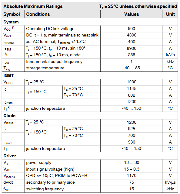
(1) Absolute maximum rated value
Category parameter symbol condition description numerical unit
System VCC working DC link voltage 900 V
Visol DC for 1 second, main terminal to heat sink 4300 V
It (RMS) per AC terminal, terminal temperature<115 ℃ 400 A
IFSM junction temperature Tj=150 ℃, pulse width tp=10ms, sine 180 ° 6900 A
I ² t Tj=150 ℃, tp=10ms (diode) 238 kA ² s
Tstg storage temperature -40~85 ℃
IGBT VCES Tj=25℃ 1200 V
IC Tj=150℃,Ts=25℃ 1145 A
IC Tj=150℃,Ts=70℃ 882 A
ICnom rated current 1200 A
TJ junction temperature (note: -40~150 ℃) -40~150 ℃
Diode VRRM Tj=25 ℃ 1200 V
IF Tj=150℃,Ts=25℃ 925 A
IF Tj=150℃,Ts=70℃ 700 A
IFnom rated forward current 930 A
Tj junction temperature -40~150 ℃
Driver Vs power supply voltage 13~30V
ViH input signal high level voltage 15+0.3 V
VisolPD QPD≤10pC, 1170 V from the primary side to the power end
Dv/dt secondary to primary voltage change rate of 75 kV/μ s
FSW switch frequency 15 kHz
(2) Key characteristic parameters
Category parameter symbol condition description Minimum value Typical value Maximum value Unit
IGBT VCE (sat) IC=600A, Tj=25 ℃ (at the terminal) 1.7-2.1 V
VCE (sat) IC=600A, Tj=125 ℃ (at the terminal) -1.9-V
Eon+Eoff IC=600A,VCC=600V,Tj=125℃ - 221 - mJ
Eon+Eoff IC=600A,VCC=900V,Tj=125℃ - 390 - mJ
Rth (j-s) each IGBT switch, junction to heat sink thermal resistance -0.03 K/W
Diode VF (VEC) IF=600A, Tj=25 ℃ (at the terminal) 1.50-1.80 V
Err IF=600A,VR=600V,Tj=125℃ - 42 - mJ
Err IF=600A,VR=900V,Tj=125℃ - 56 - mJ
Rth (j-s) each diode switch, junction to heat sink thermal resistance -0.058 K/W
Driver Is current formula: 240+k1fsw+k2IAC (k1=29mA/kHz, k2=0.00065mA/A ²) --- mA
ITRIPSC overcurrent trip level 1470 1500 1530 A (peak)
Tttrip over temperature trip level 110 115 120 ℃
System Rth (r-a) flow rate=460m ³/h, Ta=25 ℃, altitude 500m -0.0344 K/W
LCE commutation inductor -6- nH
W Weight without heat sink -1.7kg
WH heat sink weight -4.4kg
Isolation and environmental requirements
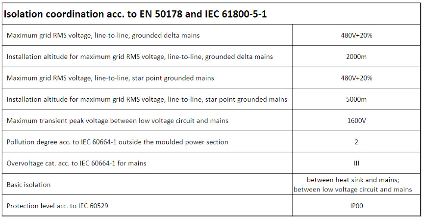
(1) Isolation coordination (compliant with EN 50178 and IEC 61800-5-1)
Grid voltage: The maximum RMS value of the grounding triangle grid line voltage is 480V+20%, corresponding to an installation altitude of 2000m; the maximum RMS value of the star point grounding grid line voltage is 480V+20%, corresponding to an installation altitude of 5000m;
Transient voltage: The maximum transient peak voltage between the low-voltage circuit and the power grid is 1600V;
Protection level: The heat sink is basically isolated from the power grid, with a protection level of IP00 (compliant with IEC 60529);
Pollution level: molded power part external pollution level 2 (compliant with IEC 60664-1);
Overvoltage category: Grid side overvoltage category III (compliant with IEC 60664-1).
(2) Environmental conditions (compliant with IEC 60721)
Environmental scenario, climate conditions, biological conditions, chemical active substances (excluding salt spray), mechanical active substances, mechanical conditions, pollution of fluids
Storage: 1K2 1B1 1C2 1S1 1M3 (customer customized packaging without declaration)-
Transport 2K2 (extended temperature range -40~85 ℃, shortened operating life near 85 ℃) 2B1 2C1 2S1--
Weather protection fixed use 3K3/1 3B1 3C2 3S1 3M6 (3M7 is feasible but limited by external components)-
Ground installation operation 5K1m 5B1 5C2 5S1 5M3 (no foreign objects/stone impact) 5F1
Ship Environment Operation -6B1 6C2 6S1 6M3-
Other key information
Thermal characteristic chart: including IGBT/diode output characteristics, energy loss (E=f (Ic, VCC)), flow rate and voltage drop/thermal resistance relationship, transient thermal impedance and other charts (as shown in Figure 1-9), which can be used for thermal design and loss calculation;
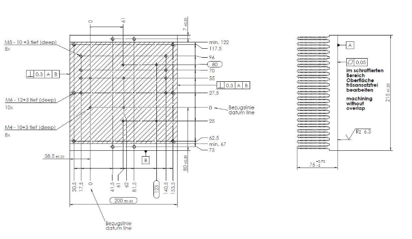
Mechanical dimensions: Provide detailed installation dimensions for modules and heat sinks (such as bolt specifications M4/M5/M6/M8, installation depth, spacing, etc.), which need to be mechanically assembled according to the drawing parameters;
Electrostatic sensitivity: It belongs to electrostatic discharge sensitive devices (ESDS) and should be operated in accordance with the specifications in Chapter 9 of IEC 60747-1;
- OMRON
- ABB
- General Electric
- EMERSON
- Honeywell
- HIMA
- ALSTOM
- Rolls-Royce
- MOTOROLA
- Rockwell
- Siemens
- Woodward
- YOKOGAWA
- FOXBORO
- KOLLMORGEN
- MOOG
- KB
- YAMAHA
- BENDER
- TEKTRONIX
- Westinghouse
- AMAT
- AB
- XYCOM
- Yaskawa
- B&R
- Schneider
- KONGSBERG
- NI
- WATLOW
- ProSoft
- SEW
- ADVANCED
- Reliance
- TRICONEX
- METSO
- MAN
- Advantest
- STUDER
- DANAHER MOTION
- Bently
- Galil
- EATON
- MOLEX
- DEIF
- B&W
- ZYGO
- Aerotech
- DANFOSS
- Beijer
- Moxa
- Rexroth
- Johnson
- WAGO
- TOSHIBA
- BMCM
- SMC
- HITACHI
- HIRSCHMANN
- Application field
- XP POWER
- CTI
- TRICON
- STOBER
- Thinklogical
- Horner Automation
- Meggitt
- Fanuc
- Baldor
- SHINKAWA
- Other Brands
- UniOP
- KUKA
- Iba
- Beckhoff
-
 OMRON C60H C6DR DE V1 Sysmac PLC
 -
 MITSUBISHI ELECTRIC A2ACPU21 S1 CPU Module
 -
 ABB BAILEY INNPM12 Network Process Module
 -
 HONEYWELL 620 0073C IPC PLC Module
 -
 Mitsubishi 15050 PR02B PLC Circuit Board
 -
 SIEMENS 6SY7000 0AC37 Drive Control Module
 -
 OMRON TJ2 ECT16 Traxial EtherCAT Controller
 -
 GE Fanuc IC698PSD300D Power Supply Module
 -
 Texas Instruments Series 505 16 Position Base
 -
 OMRON YASKAWA SGDH 10DE OY Servo Drive
 -
 Allen‑Bradley 440G-MT Safety Interlock Switch Specs
 -
 Rubycon PD27A 24V 8A Power Supply Module
 -
 SK-H1-GDB1-F11D PLC Gate Driver Board Kit
 -
 VIPA 441-4UA14 451-4UA14 PLC Module Rack
 -
 Mitsubishi FX5U-80MT ESS PLC Controller Specs
 -
 Mitsubishi Q64TCRTN Temperature PLC Module
 -
 GE 1C31170G Rev10 PLC Circuit Board Module
 -
 Schneider TWDLMDA40DTK PLC Controller Module
 -
 Omron FQM1-MMA22 Motion Control Module Specs
 -
 OMRON CJ1W-NCF71 Position Control Unit Specs
 -
 Schneider TSXETY4103 Ethernet Module
 -
 Mitsubishi Q12PHCPU Process CPU
 -
 Yaskawa 3G3HV-A4022-CE AC Drive
 -
 Cincinnati Milacron 3-533-0669G Temperature Control Board
 -
 Allen Bradley 20AC030A3AYNANC0 PowerFlex 70 Drive
 -
 Siemens 6ES7314-6BG03-0AB0 CPU 314C-2 DP
 -
 Carrier 17EX54007903 PLC Module
 -
 OMRON CS1W-V600C12 ID Controller Module
 -
 Honeywell 51402755-100 PCB Card
 -
 Heidenhain ECN 113 Rotary Encoder
 -
 OMRON B7AM-8B16 I/O Terminal Block
 -
 Fanuc A06B-6110-H026 Power Supply Module
 -
 Schneider TSXETG3021 Ethernet Gateway
 -
 OMRON CS1W-CLK21-V1 Controller Link Unit
 -
 NP1W6406T-Z704 PLC I/O Module
 -
 OMRON CJ1W-DA08C Analog Output Module
 -
 Yaskawa 3G3HV-A4022-CE AC Drive
 -
 OMRON NB7W-TW01B CP1L-EL20DR-D Power Panel
 -
 OMRON C500-NC103-E Position Control Unit
 -
 Steag Hamatech PLC DCS Servo Control System
 -
 Siemens 6SN1123-1AA00-0DA1 Power Supply Module
 -
 GE IC693CHS391H CPU & AD693CMM301A PLC Module
 -
 Siemens 6FC5303-0AF23-1AA1 PLC Control Panel
 -
 Square D CM4000T PowerLogic Circuit Monitor J1 F16
 -
 Siemens 6FX5002-5DG10-1BA0 MOTION-CONNECT 500 Cable
 -
 Schmersal SRB324ST 101195504 Safety Relay 24V
 -
 Mitsubishi 15050-PR02A PLC Circuit Board Module
 -
 OMRON CQM1-AD041 Analog Input PLC Module
 -
 Beckhoff EL5042 EtherCAT PLC Terminal Module
 -
 OMRON C200HW-MC402-E Motion Control Unit
 -
 C36TC0UA1100 Industrial Temperature Controller
 -
 NL8048BC24 12 Industrial Control LCD Module
 -
 OMRON R88D Servo Drive and Motor System
 -
 OMRON CS1W CLK21 V1 Controller Link Module
 -
 OMRON YASKAWA R7M A20030 S1 D Servo Motor
 -
 SIEMENS 6AV2128 3KB06 0AX1 Unified Comfort Panel
 -
 Schneider Electric METSEPM8240 PowerLogic Meter
 -
 Advanced AMCI 1PLC 1 31F Programmable Limit Switch
 -
 ABB PM582 ETH Programmable Logic Processor
 -
 SIEMENS 6FC5110 0CB01 0AA0 CPU Control Board
 -
 Schleicher P03GS13A CPU Module
 -
 Siemens 6SN1123-1AA00-0BA1 Power Module
 -
 Mitsubishi A1S61PN Power Supply Module
 -
 Yaskawa CPS-IONB DC Power Supply Module
 -
 Siemens 6ES7215-2BD00 CPU 215-2
 -
 Mitsubishi A2ACPU MELSEC PLC System Kit
 -
 ProSoft 3150-MCM Communication Module
 -
 Mitsubishi OSE104ET Incremental Encoder
 -
 OMRON CJ1W-AD081-V1 Analog Input Module
 -
 Broadcom BCM5464A1KRB Quad Port Ethernet IC
 -
 Modicon M221-24IO TM221C24 PLC 24 PNP Transistor
 -
 Allen-Bradley 1321-3R160-B Line Reactor 3R160B
 -
 Beckhoff CX1020-0012 Embedded PLC Module Specs
 -
 Turck BL20-PF-24VDC-D Power Feed Module Specs
 -
 Siemens 6SY7000-0AC37 Power Supply Module
 -
 Yaskawa SGDH-10DE-OY 1kW 400V Servo Drive Specs
 -
 Omron 3G3SV-BB015-E 1.5kW 220V VFD Specs
 -
 Uni-Pro CPU91-PLC J 23.020167X Processor Module
 -
 PASABAN MTC-3044 PLC Rack Power Supply 4835-A
 -
 XYCOM 3015T Operator Interface Panel BIN4.4.4
 -
 OMRON CJ1W-MD261 Mixed I/O Module
 -
 Omron NJ301-1100 PLC CPU eCat EIP Specs
 -
 Omron F500-C15-ETN Vision System PLC Module
 -
 Modicon M241-24IO TM/T2UK PLC with Ethernet
 -
 SIXNET YS-800-001 RTU PLC Module
 -
 BEMAC UST-202-D Interface Board 1307D V08B2
 -
 Yaskawa JANCD-MMOIC-02 Drive Circuit Board
 -
 ABB 3BSE005028R1 SDCS-COM-1 Comm Board
 -
 Omron 3G3MX2-A4110 A4150 Inverter Drives Specs
 -
 KEYENCE CA-E100 PLC Module
 -
 GE IC693ALG223-GB Analog Input Module Specs
 -
 ABB BAILEY IMMFP01 Multi Function Processor System
 -
 SIEMENS 6FC5372 0AA00 0AA1 NCU 7202 Controller
 -
Modicon TM241CE4 40I O Transistor Programmable Controller
-
 SIEMENS 6ES7 315 2EH13 0AB0 CPU 3152 PN DP
 -
 NORIS A1 91 PCB Card Rack Module System
 -
 SIEMENS 6ES7 313 5BE01 0AB0 Compact CPU
 -
 SCHNEIDER ELECTRIC S144B MICROLOGIC 60A Trip Unit
 -
 CNI PLC269 v3 Control Module Board Rev H
 -
ABB BAILEY IIMCP02 Processor Module
-
 OMRON NT20S ST121 EV3 Operator Interface Terminal
 -
 OMRON NS-CA001 Video Input Unit
 -
 GE Fanuc IC695CHS012 RX3i Backplane
 -
 Allen Bradley 2711E-K14C6 PanelView 1400e Terminal
 -
 Siemens Sinamics CCB 10000432.71 Power Cell
 -
 Siemens 6SL3210-1SE21-8UA0 Power Module PM340
 -
 Yaskawa CIMR-F7A20P4 AC Drive
 -
 Beckhoff EP1918-0002 EtherCAT Box I/O Module
 -
 OMRON CQM1-TC001 Temperature Control Module
 -
 GE Fanuc SGHA36AT0400 Industrial Contactor
 -
 OMRON NJ501-1500 PLC Machine Automation Controller
 -
 Mitsubishi MAZAK QX084 Power Supply MELDAS 500 CNC
 -
 B&R 0AC808.9 PLC Automation Module
 -
 OMRON CP1H-XA40DT1-D PLC Module
 -
 G&W Electric PLC15 5111 011 15kV Capnut Assembly
 -
 GE DS200SLCCG3AGH PCB Circuit Board
 -
 Siemens SINUMERIK 6FC3981-4FD PLC Extension
 -
 OMRON F300-DC I/O Image Processing Unit
 -
 FANUC A06B-0314-B002 AC Servo Motor
 -
 GC-S84 Programmable Controller Logic Module
 -
 PASABAN MONTELEC MTC3001-DC Drive Control PLC
 -
 Allen Bradley 100E460EJ11 Auxiliary Contactor
 -
 Bosch Rexroth 1070075337-101 Card Parameters
 -
 HMS Anybus AB7646-F Gateway Specifications
 -
 Bosch 062633-303401 CNC Servo PLC Card
 -
 TI 500-5023 Series PLC Power Supply
 -
 Siemens C98043-A7002-L1-12 Circuit Board
 -
 Omron E5CC-RX3A5M-000 Controller


