

Series: Siemens SIPLUS NET SCALANCE X series, full name SIPLUS SCALANCE X204-2, designed based on 6GK5204-2BB10-2AA3, specifically for medium stress environments. The document version date is April 13, 2017, and was last modified on April 5, 2017. The content may be adjusted with product iteration.
Core positioning: Management type industrial Ethernet switch, supporting PROFINET-IO device functions, integrated redundancy manager, suitable for industrial communication scenarios that require stability and redundancy, with electronic manual (CD format) and optional C-type plug.
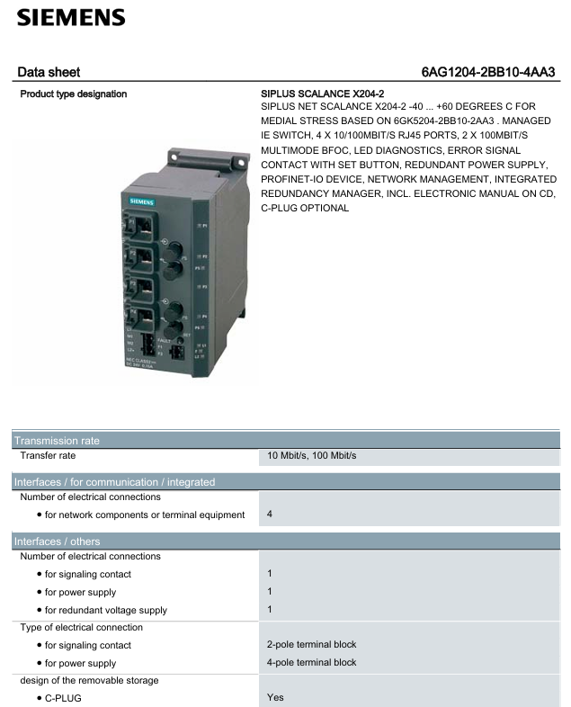
Siemens 6AG1204-2BB10-4AA3 Ethernet Switch
Product basic information
Product model: 6AG1204-2BB10-4AA3
Series: Siemens SIPLUS NET SCALANCE X series, full name SIPLUS SCALANCE X204-2, designed based on 6GK5204-2BB10-2AA3, specifically for medium stress environments. The document version date is April 13, 2017, and was last modified on April 5, 2017. The content may be adjusted with product iteration.
Core positioning: Management type industrial Ethernet switch, supporting PROFINET-IO device functions, integrated redundancy manager, suitable for industrial communication scenarios that require stability and redundancy, with electronic manual (CD format) and optional C-type plug.
Core hardware and electrical specifications
(1) Interface configuration
Number and specifications of interface types
Four 10/100Mbit/s RJ45 Ethernet ports for connecting network components or terminal devices
Ethernet optical ports with 2 100Mbit/s multi-mode BFOC optical ports, supporting optical signal transmission and compatible with multi-mode optical fibers
One 2-pole terminal block for signal contact interface, used for external signal feedback
1 4-pole terminal block (main power supply)+1 redundant power interface for power interface, supporting redundant power supply and improving system reliability
Storage expansion supports C-PLUG removable storage for configuring backups, firmware updates, etc
(2) Power supply and power consumption
Parameter category specific specifications
Power supply type: direct current (DC) power supply
The normal power supply range is 24V, and the allowable range is 18-32V
Input protection built-in fuse, specification 0.6A/60V, to prevent overcurrent damage to equipment
Current and Power Consumption Maximum Consumption Current 0.215A, Typical Power Consumption 6.36W at 24V DC
Electrical parameters of signal contacts: rated operating voltage 24V DC, maximum operating current 0.1A
(3) Machinery and Protection
Parameter category specific specifications
Dimensions width 60mm, height 125mm, depth 124mm, compact design, saving installation space
Weight net weight 0.78kg, lightweight and easy to install
Installation methods support 35mm DIN rail installation, wall installation, S7-300 rail installation, suitable for various industrial site layouts
Protection level IP30, can prevent solid foreign objects from entering (diameter>2.5mm), suitable for installation in control cabinets
Environmental adaptability
(1) Temperature and humidity
Environmental condition range requirements
Working temperature -40 ° C to+60 ° C, suitable for high and low temperature industrial environments
Storage/transportation temperature -40 ° C to+70 ° C, meeting harsh transportation and storage needs
Maximum 100% without condensation at a relative humidity of 25 ° C, condensation/frosting allowed (not adjustable in condensation state)
(2) Special environmental tolerance
Pressure and altitude:
-1080hPa-795hPa (altitude -1000m to+2000m): operating temperature -40 ° C to+60 ° C
-795hPa-658hPa (altitude+2000m to+3500m): operating temperature -40 ° C to+50 ° C
-658hPa-540hPa (altitude+3500m to+5000m): operating temperature -40 ° C to+40 ° C
Biological/Chemical/Mechanical Tolerance: Complies with EN 60721-3-3 standard,
-Bioactive substances: 3B2 grade (resistant to mold, fungi, sponge spores, excluding animals)
-Chemical active substance: Grade 3C4 (including EN 60068-2-52 salt spray test, Grade 3)
-Mechanical active substance: 3S4 level (resistant to sand and dust), unused interfaces need to be covered with dust caps
(3) Compliance in hazardous areas
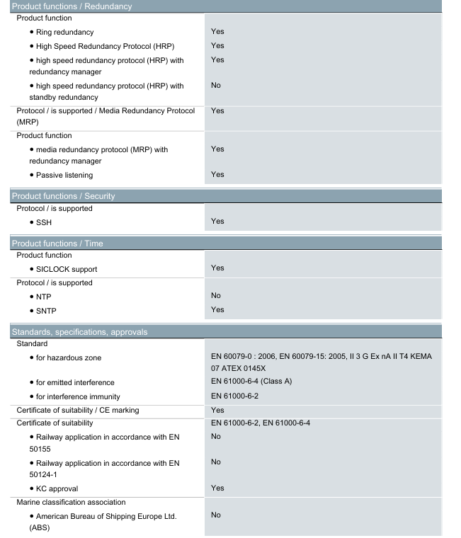
Compliant with EN 60079-0:2006 and EN 60079-15:2005 standards, certified level II 3 G Ex nA II T4 KEMA 07 ATEX 0145X, suitable for use in hazardous areas of the corresponding level.
Functional characteristics
(1) Network Management and Configuration
Specific abilities of functional categories
Management methods support CLI (Command Line Interface), web-based management, MIB support, STEP 7 configuration, and multiple ways to adapt to different user habits
Alarm and log support sending TRAP alarms via email for remote monitoring; Support port diagnosis, packet size/type statistics, error statistics, and assist in fault location
Protocol support - Basic protocols: Telnet, HTTP, HTTPS, TFTP, FTP, DCP, LLDP
-SNMP protocol: v1/v2/v3, meeting network management requirements of different security levels
-Security protocol: SSH, ensuring remote management communication security
(2) Redundancy and Topology
Specific abilities of functional categories
The redundancy protocol supports MRP (Media Redundancy Protocol) and HRP (High Speed Redundancy Protocol), integrates a redundancy manager, and does not support HRP backup redundancy
Redundancy performance: When cascading redundant loops, the reconstruction time is less than 0.3s, quickly restoring communication and reducing the impact of faults
Topology supports star topology that can be cascaded arbitrarily (limited only by signal propagation time), suitable for complex industrial network layouts
(3) Other key functions
DHCP function: Supports DHCP clients, can automatically obtain IP addresses, and simplifies network configuration.
Time synchronization: Supports SICLOCK and SNTP protocols, but does not support NTP to ensure time consistency of network devices.
PROFINET Function: As a PROFINET-IO device, it supports PROFINET IO diagnostics but does not support IRT (Real Time) function.
Port function: Supports port mirroring, facilitating network traffic analysis and troubleshooting.
Certification and Compliance
(1) Basic certification
CE certification, KC certification, in compliance with EN 61000-6-2 (anti-interference) and EN 61000-6-4 (interference emission, Class A) electromagnetic compatibility standards.
(2) Special scenario authentication
Not supporting railway applications (EN 50155, EN 50124-1 standards), not supporting maritime classification society certification (ABS, BV, DNV, etc.), only applicable to conventional industrial and hazardous area scenarios.
- User name Member Level Quantity Specification Purchase Date
- Satisfaction :
-


-
 SUMITOMO T2100Z steel turning selection and troubleshooting
 -
 SUMITOMO PSZ Turn Quick Change System Selection and Troubleshooting
 -
 SUMITOMO EGU chip breaker selection and troubleshooting
 -
 SUMITOMO GND slotting tool holder selection and troubleshooting
 -
 SUMITOMO AC8000P steel turning selection and troubleshooting
 -
 SUMITOMO AC6000M Stainless Steel Turning Guide
 -
 SUMITOMO ELECTRIC AC5000S Heat Resistant Alloy Turning Guide
 -
 SUMITOMO ELECTRIC AC4000K Cast Iron Turning Selection Guide
 -
 SUMITOMO ELECTRIC AC1135U Small Parts Turning Application Guide
 -
 SUMITOMO ELECTRIC AC1030U Precision Machining Selection and Practice for Small Parts
 -
 CCS 6900G/P pressure switch
 -
 BENDER WR Transformer Selection
 -
 BENDER RCMA475LY Residual Current Monitoring
 -
 BENDER IRDH575 Insulation Monitoring
 -
 BENDER IRDH265 Insulation Monitoring and Debugging
 -
 Bender RCMA475LY residual current monitor debugging
 -
 Beckwith Electric M-3425A Generator Protection Relay Debugging Guide
 -
 Automated MEX816U Expander Troubleshooting Guide
 -
 ASEM HT2150 Industrial Tablet Selection and Troubleshooting
 -
 Troubleshooting and practical application of Advantest U3771/3772 microwave spectrum analyzer
 -
 Advantest R6144 Programmable DC Voltage/Current Source (Calibration Source) Calibration and Maintenance
 -
 Aerotech UNIDEX 100/U100i single axis motion controller
 -
 Aerotech Ndrive MP Ultra Compact PWM Digital Servo Driver
 -
 Aerotech Ndrive HPe 10/20/30 High Performance PWM Digital Servo Drive
 -
 Aerotech Ndrive HLe maintenance replacement
 -
 Aerotech Ndrive CP maintenance replacement
 -
 Aerotech Ndrive Linear Drive Selection
 -
 Aerotech NDrive HL linear drive maintenance replacement
 -
 Aerotech NDrive HP 10/20/30 Maintenance and Replacement
 -
 Aerotech NDrive CP10 Servo Drive Guide
 -
 SIGMATEK TAE1941 Display Unit Replacement and Troubleshooting
 -
 SIGMATEK TAE151 Replacement and Troubleshooting
 -
 SIGMATEK AKM Servo Motor Replacement and Troubleshooting Guide
 -
 SIGMATEK S-DIAS Control System Replacement and Upgrade Guide
 -
 SIGMATEK ETT Series HMI Replacement and Selection Guide
 -
 SIGMATEK DIAS Drive 310-23 servo amplifier
 -
 SIGMATEK CCP 521 C-DIAS processor module
 -
 Megmeet L6 electric drive troubleshooting
 -
 Sysmex XN-1000/2000 Technical Guide
 -
 Sysmex XN-L blood analyzer maintenance and troubleshooting
 -
 Troubleshooting and Maintenance of Sysmex XN-9000
 -
 LTI Motion ServoOne PROFIBUS/PROFINET Troubleshooting and Replacement
 -
 Micro Innovation MICRO GF1 Touch Screen Troubleshooting and Replacement
 -
 Troubleshooting and Replacement of Micro Innovation WINbloc Distributed I/O System
 -
 MICRO PANEL GS-2 Troubleshooting and Debugging
 -
 LTi Synchronous Motor LST/LSH Replacement Selection Guide
 -
 Fault diagnosis of LTi CDE/CDB3000
 -
 Maintenance and troubleshooting of ENOTEC SILOTEC 8000 silo analyzer
 -
 ENOTEC ENSITU 7000 Oxygen Analyzer
 -
 ENOTEC COMTEC 6000 ATEX GasEx Analyzer Maintenance, Calibration, and Troubleshooting Guide
 -
 ENOTEC Analyzer Family Selection Guide
 -
 ENOTEC OXITEC 500E Oxygen Analyzer
 -
 KUKA KR CS Box-2 Compact Controller for Four Axis SCARA Robot
 -
 KUKA KR C5 slim-2 Robot Controller
 -
 KUKA KR C5 micro KSS troubleshooting
 -
 KUKA KR C5 micro debugging and troubleshooting
 -
 KUKA KR C5 Controller Assembly and Troubleshooting
 -
 KUKA KR C5 Cabinet Assembly and Troubleshooting
 -
 KUKA KR C4 Smallsize-2 Debugging Guide
 -
 KUKA KR C4 Midsize Assembly Guide
 -
 ENOTEC OXITEC 5000 Oxygen Analyzer Maintenance Guide
 -
 KUKA KR C4 extended assembly and debugging
 -
 KUKA KR C4 compact assembly and debugging
 -
 KUKA Sunrise Cabinet Med Medical Collaborative Robot Special Control Cabinet
 -
 KUKA Sunrise Cabinet Next Generation Small Control Cabinet
 -
 KUKA KR C4 Smallsize-2 family's smallest control cabinet
 -
 KUKA KR C4 Midsize Fault Diagnosis
 -
 KUKA KR C4 extended is a high-power multi axis control cabinet
 -
 Troubleshooting and Maintenance of KUKA KR C4 Control Cabinet
 -
 Troubleshooting and Maintenance of KUKA KR C4 Compact Control Cabinet
 -
 KUKA KR15 DELTA-2 V2 Robot Installation and Debugging
 -
 KUKA TITAN-2 Ultra Assembly and Maintenance Guide
 -
 KUKA KR SCARA-2 CS Assembly, Debugging, and Operation Guide
 -
 Troubleshooting KUKA SCARA X
 -
 Troubleshooting of KUKA KR FORTEC-2 ultra
 -
 Troubleshooting of KUKA KR FORTEC-2
 -
 Troubleshooting KUKA KR 1000 Titan
 -
 Troubleshooting of KUKA KR 600 FORTEC
 -
 KUKA KR 500 MT FORTEC Maintenance and Inspection
 -
 KUKA KR 360 FORTEC Inspection and Maintenance Guide
 -
 Troubleshooting KUKA Sunrise Cabinet Med
 -
 KUKA KR SCARA HO Assembly and Maintenance
 -
 KUKA QUANTEC-2 PA maintenance troubleshooting
 -
 KUKA QUANTEC-2 K/P Maintenance Troubleshooting Guide
 -
 KUKA QUANTEC-2 HO Maintenance Guide
 -
 KUKA KR QUANTEC-2 HC Maintenance and Rescue Guide
 -
 KUKA KR QUANTEC-2 Maintenance Troubleshooting Guide
 -
 KUKA KR QUANTEC PA series heavy-duty palletizing robot
 -
 KUKA KR IONTEC-2 Debugging and Maintenance Guide
 -
 KUKA KR IONTEC ultra series six axis heavy-duty industrial robot
 -
 KUKA KR IONTEC HO Maintenance Troubleshooting Guide
 -
 KUKA KR CYBERTECH-3 HW maintenance troubleshooting
 -
 KUKA KR CYBERTECH-3 maintenance troubleshooting
 -
 KUKA KR8 R2100-2 arc HW maintenance troubleshooting
 -
 KUKA KR CYBERTECH nano-2 maintenance troubleshooting
 -
 KUKA KR 20 R1810 HO maintenance troubleshooting
 -
 KUKA CYBERTECH maintenance troubleshooting
 -
 KUKA KR CYBERTECH CR maintenance troubleshooting
 -
 KUKA KR AGILUS-3 ultra maintenance troubleshooting
 -
 KUKA KR 300 R2700-2 C-F maintenance troubleshooting
 -
 KUKA KR 20 R1820-2 E Maintenance Troubleshooting and Replacement Practice
 -
 KUKA AGILUS-3 troubleshooting
 -
 KUKA KR AGILUS-2 maintenance troubleshooting
 -
 KUKA KR 1000 titan PA troubleshooting
 -
 KUKA KR 700 PA maintenance troubleshooting
 -
 KUKA KR18 R1450-3 PP Operation and Maintenance Essentials
 -
KUKA KR12 SCARA Operations Essentials
-
 KUKA KR4 R600 Operation and Maintenance Essentials
 -
 KUKA KR 3 AGILUS Operation and Maintenance Safety Essentials
 -
 KUKA LBR iiwa CR Cleanroom Troubleshooting and Maintenance
 -
 Troubleshooting and Maintenance of KUKA KR AGILUS sixx
 -
 KUKA KR60 SCARA CS Maintenance Guide
 -
 KUKA KR 23 SCARA-2 Robot Installation and Maintenance Detailed Explanation
 -
 KUKA KR 20 SCARA CS Robot Selection and Maintenance Guide
 -
 KUKA KR 15 DELTA-2 Robot Installation and Maintenance
 -
 KUKA KR 13 SCARA-2 CS Detailed Explanation
 -
 KUKA KR 3 D1200 Robot Operation and Maintenance
 -
 KUKA KR 3 D1200 HM Robot Operation and Maintenance Guide
 -
 KUKA LBR Med Medical Robot Integration Guide
 -
 KUKA iiwa Robot Safety Operation and Maintenance
 -
 KUKA LBR iiwa CR Operations and Troubleshooting
 -
 Lauer PCS Series Operation Console Configuration Guide
 -
 Installation and Maintenance Guide for KUKA LBR iisy Series Collaborative Robots
 -
 KUKA LBR iisy 3 R760 Collaborative Robot Debugging Guide
 -
 KUKA LBR iico Robot Installation and Debugging Technical Guide
 -
 Lauer Starline LCA 300/320/325 Text Display Application Guide
 -
 Lauer PCS 950 Operation Console Application Guide
 -
 Lauer EPC series industrial computer configuration


