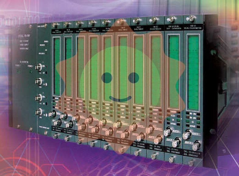
Zygo 8010-0105-02 ZMI-501 is a high-performance displacement measurement interferometer belonging to the ZYGO ZMI series precision measurement equipment category. Its core function is to achieve nanometer level precision detection and feedback of target object displacement through laser interference principle. As a key detection device in the ZYGO measurement ecosystem, it can work in conjunction with components such as measurement electronic boards and specialized cables in the same series, providing stable and accurate displacement data support for semiconductor manufacturing, precision machining, scientific research experiments, and other fields. It is a core tool to ensure the operational accuracy and product quality of high-end equipment.
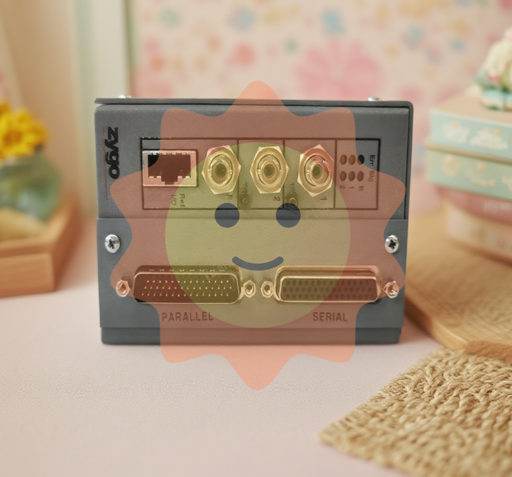
Zygo 8010-0105-02 ZMI-501 Displacement Measurement Interferometer
Product core positioning
Zygo 8010-0105-02 ZMI-501 is a high-performance displacement measurement interferometer belonging to the ZYGO ZMI series precision measurement equipment category. Its core function is to achieve nanometer level precision detection and feedback of target object displacement through laser interference principle. As a key detection device in the ZYGO measurement ecosystem, it can work in conjunction with components such as measurement electronic boards and specialized cables in the same series, providing stable and accurate displacement data support for semiconductor manufacturing, precision machining, scientific research experiments, and other fields. It is a core tool to ensure the operational accuracy and product quality of high-end equipment.
Key technologies and performance parameters
Parameter category
Core indicators (derived based on ZYGO ZMI series interferometer standards and industrial grade characteristics)
Measurement accuracy
Displacement measurement resolution as low as 0.05 nm, measurement error ≤ ± 0.1 nm (within the full range)
Measurement range
The standard range can reach 10 meters, and longer distance measurements can be achieved through expansion modules (supporting up to 50 meters)
Characteristics of laser light source
Built in helium neon laser source, wavelength 632.8 nm, output power ≥ 0.5 mW, wavelength stability ≤± 0.005 nm/℃
Measuring speed
The maximum measurement speed reaches 5 m/s and supports switching between dynamic and static displacement measurement modes
Signal output interface
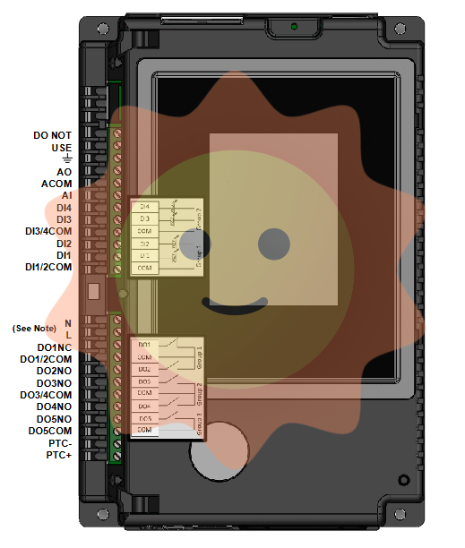
Equipped with HSSDC2 high-speed data interface (compatible with ZYGO 1115-800-055 cable) and analog output interface (0-10V)
Environmental adaptability
Working temperature range: 0 ℃~40 ℃, relative humidity ≤ 85% (no condensation), with automatic temperature and pressure compensation function
Data update rate
The highest data update rate is 1 MHz, which meets the requirements of high-frequency dynamic displacement monitoring
Core functions and technological advantages
1. Optimization of laser interferometry measurement technology
This interferometer is based on the classical laser interference principle and optimized with ZYGO exclusive technology to achieve high-precision measurement:
Multi wavelength adaptation: In addition to the default 632.8 nm helium neon laser wavelength, the 1064 nm near-infrared laser can be adapted by changing the laser module to meet the detection needs of different materials and measurement environments, avoiding absorption or reflection interference of specific wavelength lasers by target objects;
Anti interference algorithm: Equipped with advanced signal denoising and interference suppression algorithms, it can effectively filter out the influence of external factors such as environmental vibration (measurement error amplification ≤ 0.02 nm when vibration frequency ≤ 500 Hz) and electromagnetic radiation on the measurement signal, ensuring data stability;
Real time compensation function: Integrated temperature, air pressure, and humidity sensors can collect environmental parameters in real time and automatically compensate for measurement results. For example, for every 1 ℃ change in temperature, the compensation accuracy can reach ± 0.01 nm, avoiding measurement deviation caused by environmental changes.
2. Collaborative advantages with components of the same series
Compared to standalone ordinary interferometers, Zygo 8010-0105-02 ZMI-501 has significant advantages when working in conjunction with other ZYGO devices:
Seamless compatibility feature: It can be directly connected to the ZYGO ZMI 4104C measurement electronic board through the HSSDC2 interface (using 1115-800-055 cable), without the need for additional conversion modules, reducing signal transmission links, lowering data loss and delay, with data transmission delay ≤ 10 μ s;
System linkage calibration: supports linkage with ZYGO laser heads (such as 7730 model) and differential interferometer modules (DPMI), and achieves automatic calibration between devices through built-in calibration programs. The calibration accuracy is ≤± 0.03 nm, greatly simplifying the calibration process and improving the overall measurement accuracy of the system;
Data integration capability: It can be integrated with the ZYGO dedicated measurement software platform to achieve synchronous data collection, real-time visualization display, and historical data storage for multiple devices (supporting data export formats: CSV, Excel, TXT), making it convenient for users to conduct data analysis and report generation.
Adapt system components and application scenarios
1. Core adaptation system components
Based on the ZYGO measurement ecosystem, the typical adaptation combination of this interferometer is as follows:
Signal receiving and processing unit: ZYGO ZMI 4104C measurement electronic board, ZMI 6100 high-end control unit;
Signal transmission components: ZYGO 1115-800-055 HSSDC2-HSSDC2 cable, 1115-801-346 laser head dedicated cable;
Auxiliary calibration equipment: ZYGO standard length calibration block (accuracy ± 0.01 nm), environmental parameter monitoring module;
Software platform: ZYGO Mx measurement and analysis software, customized data processing system (supporting API interface development).
2. Key application scenarios
In the field of semiconductor manufacturing, it is used for monitoring the displacement of silicon wafer worktable in wafer lithography equipment with 7nm and below processes, providing real-time feedback on worktable position deviation, ensuring the accuracy of lithography pattern overlay (overlay error ≤ 0.3 nm), and guaranteeing the quality of chip manufacturing;
In the field of precision machining: real-time detection of spindle displacement and guide rail motion accuracy of high-end CNC machine tools, dynamically adjusting equipment parameters during the machining process to control the dimensional accuracy of machined parts within ± 0.5 nm, meeting the machining needs of high-end fields such as aerospace and medical equipment;
In the field of scientific research experiments, it is used for micro displacement control and monitoring of sample stages in research equipment such as atomic force microscopy (AFM) and scanning electron microscopy (SEM), providing accurate displacement data support for experiments such as nanomaterial research and biological molecular structure analysis;
In the field of optical equipment testing, the displacement deviation of astronomical telescope lenses, laser resonators and other optical equipment is detected and calibrated to ensure the alignment accuracy of the optical system, improve the imaging quality of the equipment and the stability of laser output.
Precautions for use and maintenance standards
1. Installation and operation requirements
Installation environment selection: It should be installed in an environment without strong vibration (vibration acceleration ≤ 0.1 m/s ²) and strong electromagnetic interference (electric field strength ≤ 10 V/m, magnetic field strength ≤ 1 mT), avoiding direct sunlight on the optical components of the equipment and preventing laser wavelength drift;
Optical component protection: During installation and debugging, dust-free gloves should be worn to avoid finger contact with optical lenses (such as interferometer lenses and laser output windows). If the surface of the lens is contaminated with dust, it should be gently wiped with specialized lens paper dipped in anhydrous ethanol. It is forbidden to use ordinary paper towels or fabrics for wiping;
Interface connection specification: When connecting with measuring electronic boards, cables, and other components, it is necessary to ensure that the interface is aligned with the positioning pin, slowly insert and lock the buckle, and avoid violent insertion and removal that may damage the interface pins; After the connection is completed, it is necessary to check whether there is any looseness at the interface to prevent signal transmission interruption;
Parameter setting requirements: Set laser power, measurement range, data update rate and other parameters correctly according to measurement requirements. Before the first use, perform equipment initialization calibration (using ZYGO standard calibration block), save calibration data after calibration, and confirm the validity of calibration data before each subsequent use.
2. Maintenance and troubleshooting
Regular maintenance plan: Clean the optical components of the equipment every month (remove surface dust and stains), and test the power and wavelength stability of the laser source every quarter. If the power attenuation exceeds 20% or the wavelength stability exceeds the standard range, the laser module should be replaced in a timely manner; Check the internal circuits and interfaces of the equipment every six months to ensure there are no looseness, oxidation, or other issues;
Common troubleshooting:
If there are significant fluctuations in the measurement data, first check whether the environmental parameters (temperature, air pressure, humidity) exceed the operating range of the equipment. If they do, adjust the environmental conditions and perform compensation calibration again; Next, check whether the signal transmission cable is damaged, whether the interface is contaminated, and replace the spare cable if necessary;
If the laser cannot output normally, check if the laser source power supply is normal and if the laser module is damaged. If the power supply is normal but the laser does not output, contact ZYGO factory to replace the laser module;
If the data cannot be transmitted to the measuring electronic board normally, check the interface connection status and use the ZYGO signal tester to check whether the interface signal output is normal. If the interface signal is abnormal, repair or replace the equipment interface module;
Principle of replacement and maintenance: When the core components of the equipment (such as laser modules, optical lenses, signal processing chips) malfunction, ZYGO original accessories should be used for replacement. The use of third-party accessories is prohibited to avoid a decrease in measurement accuracy or damage to the equipment due to incompatible accessories; Maintenance work must be carried out by ZYGO certified engineers or professionally trained technicians to ensure maintenance quality and equipment safety.
Comparison of core differences with other similar devices in ZYGO
Comparing dimensions
Zygo 8010-0105-02 ZMI-501 displacement measurement interferometer
ZYGO ZMI 4104C Measurement Electronic Board
ZYGO 7730 laser head
Core functions
Displacement detection and data output
Measurement signal processing and analysis
Provide stable laser light source
Key performance indicators
Measurement resolution of 0.05 nm, range of 10 m
4-axis measurement, position resolution 0.15 nm
Laser power ≥ 1 mW, wavelength stability ± 0.003 nm/℃
Interface type
HSSDC2、 Analog interface
VME bus interface, HSSDC2 expansion interface
Customized laser head interface (compatible with 1115-801-346 cable)
Typical application scenarios
Displacement measurement and monitoring
Multi axis measurement signal processing
Provide light sources for interferometers and measurement systems
Relationship with other devices
Output displacement measurement signal to the measuring electronic board
Receive interferometer signals and perform data processing
Provide laser signals for interferometers
- User name Member Level Quantity Specification Purchase Date
- Satisfaction :
-


