

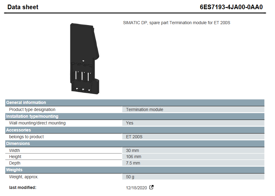
Siemens SIMATIC DP series terminal module, positioned as a spare part, designed specifically for the ET 200S distributed I/O system. Its core function is to assist in the signal terminal connection and stable transmission of the ET 200S system. The document was last modified on August 22, 2025, and the content may be adjusted with product iteration.
Siemens 6ES7193-4JA00-0AA0 Terminal Module
Product basic information
Product model: 6ES7193-4JA00-0AA0
Product type: Siemens SIMATIC DP series terminal module, positioned as a spare part, designed specifically for the ET 200S distributed I/O system. Its core function is to assist in the signal terminal connection and stable transmission of the ET 200S system. The document was last modified on August 22, 2025, and the content may be adjusted with product iteration.
Core specification parameters
(1) Installation and adaptation
Installation method: Supports wall installation/direct installation, compatible with ET 200S system, no additional installation accessories required.
Belonging product: Clearly belongs to the ET 200S series and is only used for the matching of this series of systems. It is not compatible with other series of devices.
(2) Size and weight
Parameter category specific specifications
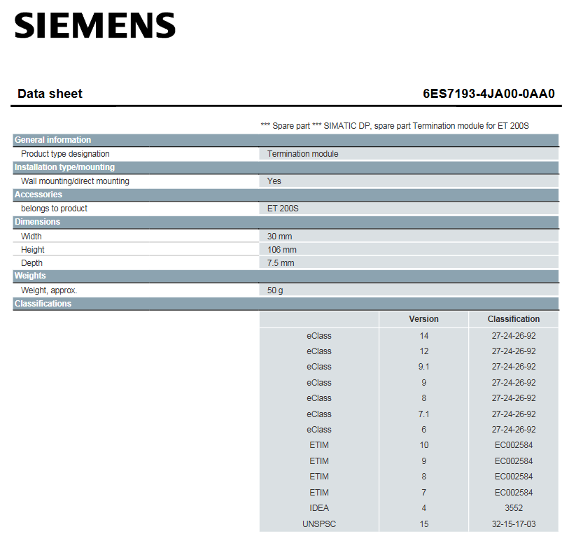
Size width 30mm, height 106mm, depth 7.5mm, compact structure, saving installation space
Weight approximately 50g, lightweight design, convenient for transportation and on-site installation and operation
Certification and Compliance
(1) Basic certification
Universal product certification, EMV (Electromagnetic Compatibility) certification, manufacturer's declaration, CE certification, EG Konf. certification, RCM certification, in compliance with safety and electromagnetic compatibility standards for basic industrial equipment, and can be used compliantly in conventional industrial environments.
(2) Special scenario authentication
Hazardous area use: Through FM certification, UL certification, and IECEx certification, it supports deployment in hazardous areas (such as industrial flammable and explosive environments) and meets special safety requirements.
Maritime applications: Certified by CCC Ex, NK (Japan Classification Society), ABS (American Bureau of Shipping), LRS (Lloyd's Register of Shipping), CCS (China Classification Society), suitable for maritime scenarios such as ships and offshore platforms, meeting the stringent standards of maritime equipment.
Precautions
Safety specifications are generally applicable to control system handling. Instructions and warnings related to a specific subject or operation of the product.
The following norms must be strictly observed:
must strictly comply with the technical specifications and typical applications of the product system
Personnel training: Only trained personnel shall install, operate, maintain or repair the product system. must
Provide guidance and explanation of the situation in danger areas to these personnel.
Unauthorized changes: Changes or structural changes to the product system may not be made.
Maintenance responsibility: Must ensure that the product system is used only under appropriate conditions and in full fitness for use.
Working environment: The user must meet the specified environmental conditions:
Safety regulation
The following safety provisions of EN 50110-1 shall be fully complied with when handling product systems (maintenance) :
1 Disconnect completely.
2 Secure to prevent reconnection.
3 Verify that the installation is complete.
4 Ground and short-circuit the device.
Warning: Only qualified maintenance personnel can remove and insert the module. In order to ensure the personal safety of the operator, before each pulling out or inserting, you must
Disconnect the power supply and ensure that there is no voltage on all terminals at the back, and the product is effectively grounded with the ground screw at the back.
Installation precautions
First, the importance of industrial equipment installation
In modern industrial production, various equipment and machines are widely used in various fields, such as manufacturing, energy industry, chemical industry and so on. The installation of industrial equipment is directly related to production efficiency and product quality. Proper installation and commissioning of good equipment can ensure the stable operation of the production line, improve production efficiency and product quality, reduce maintenance costs, and ensure the safety of employees.
Second, the steps of industrial equipment installation
1. Preparation: Before the installation of industrial equipment, it is necessary to carry out adequate preparation work. This includes the tools and equipment required for installation, cleaning and preparation of the installation site, and making installation plans and schedules.
2. Determine the installation position: Determine the installation position of the equipment according to the requirements of the equipment and the layout of the production line. When determining the location, the weight and size of the equipment need to be considered, as well as the coordination of the equipment with the surrounding environment.
3. Install the device: Assemble and install the device according to the installation instructions. Ensure that the device is securely and accurately connected, while protecting the appearance and internal components of the device.
4. Connect power supplies and pipelines: For devices that require power supplies and power supplies, properly connect power supplies and pipelines. The connection of power supply and pipeline should comply with safety standards to avoid hazards such as electric shock and leakage.
5. Commissioning the device: After the installation is complete, you need to commission the device to ensure that the device can run properly. It includes checking the functions and performance of the equipment, adjusting the parameters and Settings of the equipment, and carrying out the necessary tests and inspections.
6. Training operators: After the installation of the equipment, it is necessary to train the operators to understand the operation methods and precautions of the equipment, and improve the operation skills and safety awareness of the employees.
Third, industrial equipment installation precautions
1. Safety first: When installing industrial equipment, safety is the most important consideration. You must operate in strict accordance with safety regulations and wear necessary protective equipment to ensure the safety of the workplace.
2. Strictly follow the equipment instructions: Industrial equipment usually comes with detailed installation instructions, you must carefully read and understand the contents of the instructions, and install the operation in accordance with the requirements of the instructions.
3. Pay attention to the assembly sequence: When installing the device, follow the correct assembly sequence to ensure that all components of the device are assembled correctly to avoid equipment failures or safety accidents caused by incorrect assembly sequence.
- User name Member Level Quantity Specification Purchase Date
- Satisfaction :
-


-
 Foxboro E69F Converter
 -
 Foxboro DCS Compact200 series RH916RB (16 slot horizontal bottom plate)
 -
 Reliability Electric PSC7000 Control Card Troubleshooting and Maintenance
 -
 Eaton MTL F809F Plus DTM Operating Instructions
 -
 Motorola ACE3600 RTU Troubleshooting Guide
 -
 MOOG D136-003-001 on-site deployment and troubleshooting
 -
 Troubleshooting and Maintenance of Micro Panel GF1-10 Touchscreen
 -
 Neles NDX Intelligent Valve Positioner Troubleshooting and Debugging
 -
 Jamesbury VPVL Mod D Maintenance and Troubleshooting
 -
 Jamesbury VPVL Pneumatic actuator selection and maintenance guide
 -
 GMW IPP 144-40 GS Thermal Printer Troubleshooting Guide
 -
 Meggitt C327845 Gas Shutoff Valve Troubleshooting and Replacement Guide
 -
 Meggitt C422685 Gas Solenoid Valve Troubleshooting Guide
 -
 LTI ServoOne Servo Troubleshooting Guide
 -
 Jenaer Antriebstechnik ECOVARIO Servo Troubleshooting Guide
 -
 Honeywell TDC3000X Troubleshooting Guide
 -
 Honeywell NOTIFIER NFS2-3030 Troubleshooting Guide
 -
 Troubleshooting of Honeywell FC series safety barriers
 -
 Honeywell XL1404 Troubleshooting Guide
 -
 Honeywell TDC 3000 Troubleshooting and Module Replacement Guide
 -
 HIMA X-DI 64 01 Safety Module
 -
 Hirschmann MICE MS20/MS30 Switch Integration and Troubleshooting
 -
 EXOR ePAD05/ePAD06 button screen replacement and troubleshooting
 -
 EXOR eVO58-TST/TNT Compact HMI Human Machine Panel
 -
 Esd VME-PCM-CADDY/2 Carrier Board Integration and Troubleshooting Guide
 -
 Elmo Gold Tuba Servo Drive Integration and Troubleshooting Guide
 -
 Eaton COM-MPB1-TP/MPB2-TP communication module
 -
 DeltaTau PMAC2 PCI Ultralite Programmable Multi Axis Motion Controller
 -
 DATA PATTERNS DP-VME-5114 Dual PMC Carrier Board Integration and Troubleshooting
 -
 CMZ SVM1608 Intelligent Servo Driver
 -
 SUMITOMO T2100Z steel turning selection and troubleshooting
 -
 SUMITOMO PSZ Turn Quick Change System Selection and Troubleshooting
 -
 SUMITOMO EGU chip breaker selection and troubleshooting
 -
 SUMITOMO GND slotting tool holder selection and troubleshooting
 -
 SUMITOMO AC8000P steel turning selection and troubleshooting
 -
 SUMITOMO AC6000M Stainless Steel Turning Guide
 -
 SUMITOMO ELECTRIC AC5000S Heat Resistant Alloy Turning Guide
 -
 SUMITOMO ELECTRIC AC4000K Cast Iron Turning Selection Guide
 -
 SUMITOMO ELECTRIC AC1135U Small Parts Turning Application Guide
 -
 SUMITOMO ELECTRIC AC1030U Precision Machining Selection and Practice for Small Parts
 -
 CCS 6900G/P pressure switch
 -
 BENDER WR Transformer Selection
 -
 BENDER RCMA475LY Residual Current Monitoring
 -
 BENDER IRDH575 Insulation Monitoring
 -
 BENDER IRDH265 Insulation Monitoring and Debugging
 -
 Bender RCMA475LY residual current monitor debugging
 -
 Beckwith Electric M-3425A Generator Protection Relay Debugging Guide
 -
 Automated MEX816U Expander Troubleshooting Guide
 -
 ASEM HT2150 Industrial Tablet Selection and Troubleshooting
 -
 Troubleshooting and practical application of Advantest U3771/3772 microwave spectrum analyzer
 -
 Advantest R6144 Programmable DC Voltage/Current Source (Calibration Source) Calibration and Maintenance
 -
 Aerotech UNIDEX 100/U100i single axis motion controller
 -
 Aerotech Ndrive MP Ultra Compact PWM Digital Servo Driver
 -
 Aerotech Ndrive HPe 10/20/30 High Performance PWM Digital Servo Drive
 -
 Aerotech Ndrive HLe maintenance replacement
 -
 Aerotech Ndrive CP maintenance replacement
 -
 Aerotech Ndrive Linear Drive Selection
 -
 Aerotech NDrive HL linear drive maintenance replacement
 -
 Aerotech NDrive HP 10/20/30 Maintenance and Replacement
 -
 Aerotech NDrive CP10 Servo Drive Guide
 -
 SIGMATEK TAE1941 Display Unit Replacement and Troubleshooting
 -
 SIGMATEK TAE151 Replacement and Troubleshooting
 -
 SIGMATEK AKM Servo Motor Replacement and Troubleshooting Guide
 -
 SIGMATEK S-DIAS Control System Replacement and Upgrade Guide
 -
 SIGMATEK ETT Series HMI Replacement and Selection Guide
 -
 SIGMATEK DIAS Drive 310-23 servo amplifier
 -
 SIGMATEK CCP 521 C-DIAS processor module
 -
 Megmeet L6 electric drive troubleshooting
 -
 Sysmex XN-1000/2000 Technical Guide
 -
 Sysmex XN-L blood analyzer maintenance and troubleshooting
 -
 Troubleshooting and Maintenance of Sysmex XN-9000
 -
 LTI Motion ServoOne PROFIBUS/PROFINET Troubleshooting and Replacement
 -
 Micro Innovation MICRO GF1 Touch Screen Troubleshooting and Replacement
 -
 Troubleshooting and Replacement of Micro Innovation WINbloc Distributed I/O System
 -
 MICRO PANEL GS-2 Troubleshooting and Debugging
 -
 LTi Synchronous Motor LST/LSH Replacement Selection Guide
 -
 Fault diagnosis of LTi CDE/CDB3000
 -
 Maintenance and troubleshooting of ENOTEC SILOTEC 8000 silo analyzer
 -
 ENOTEC ENSITU 7000 Oxygen Analyzer
 -
 ENOTEC COMTEC 6000 ATEX GasEx Analyzer Maintenance, Calibration, and Troubleshooting Guide
 -
 ENOTEC Analyzer Family Selection Guide
 -
 ENOTEC OXITEC 500E Oxygen Analyzer
 -
 KUKA KR CS Box-2 Compact Controller for Four Axis SCARA Robot
 -
 KUKA KR C5 slim-2 Robot Controller
 -
 KUKA KR C5 micro KSS troubleshooting
 -
 KUKA KR C5 micro debugging and troubleshooting
 -
 KUKA KR C5 Controller Assembly and Troubleshooting
 -
 KUKA KR C5 Cabinet Assembly and Troubleshooting
 -
 KUKA KR C4 Smallsize-2 Debugging Guide
 -
 KUKA KR C4 Midsize Assembly Guide
 -
 ENOTEC OXITEC 5000 Oxygen Analyzer Maintenance Guide
 -
 KUKA KR C4 extended assembly and debugging
 -
 KUKA KR C4 compact assembly and debugging
 -
 KUKA Sunrise Cabinet Med Medical Collaborative Robot Special Control Cabinet
 -
 KUKA Sunrise Cabinet Next Generation Small Control Cabinet
 -
 KUKA KR C4 Smallsize-2 family's smallest control cabinet
 -
 KUKA KR C4 Midsize Fault Diagnosis
 -
 KUKA KR C4 extended is a high-power multi axis control cabinet
 -
 Troubleshooting and Maintenance of KUKA KR C4 Control Cabinet
 -
 Troubleshooting and Maintenance of KUKA KR C4 Compact Control Cabinet
 -
 KUKA KR15 DELTA-2 V2 Robot Installation and Debugging
 -
 KUKA TITAN-2 Ultra Assembly and Maintenance Guide
 -
 KUKA KR SCARA-2 CS Assembly, Debugging, and Operation Guide
 -
 Troubleshooting KUKA SCARA X
 -
 Troubleshooting of KUKA KR FORTEC-2 ultra
 -
 Troubleshooting of KUKA KR FORTEC-2
 -
 Troubleshooting KUKA KR 1000 Titan
 -
 Troubleshooting of KUKA KR 600 FORTEC
 -
 KUKA KR 500 MT FORTEC Maintenance and Inspection
 -
 KUKA KR 360 FORTEC Inspection and Maintenance Guide
 -
 Troubleshooting KUKA Sunrise Cabinet Med
 -
 KUKA KR SCARA HO Assembly and Maintenance
 -
 KUKA QUANTEC-2 PA maintenance troubleshooting
 -
 KUKA QUANTEC-2 K/P Maintenance Troubleshooting Guide
 -
 KUKA QUANTEC-2 HO Maintenance Guide
 -
 KUKA KR QUANTEC-2 HC Maintenance and Rescue Guide
 -
 KUKA KR QUANTEC-2 Maintenance Troubleshooting Guide
 -
 KUKA KR QUANTEC PA series heavy-duty palletizing robot
 -
 KUKA KR IONTEC-2 Debugging and Maintenance Guide
 -
 KUKA KR IONTEC ultra series six axis heavy-duty industrial robot
 -
 KUKA KR IONTEC HO Maintenance Troubleshooting Guide
 -
 KUKA KR CYBERTECH-3 HW maintenance troubleshooting
 -
 KUKA KR CYBERTECH-3 maintenance troubleshooting
 -
 KUKA KR8 R2100-2 arc HW maintenance troubleshooting
 -
 KUKA KR CYBERTECH nano-2 maintenance troubleshooting
 -
 KUKA KR 20 R1810 HO maintenance troubleshooting
 -
 KUKA CYBERTECH maintenance troubleshooting
 -
 KUKA KR CYBERTECH CR maintenance troubleshooting


