
SIEMENS C500 microcontroller architecture and instruction set
Most arithmetic instructions affect the flag bits in the program state word (PSW), and engineers must pay attention when writing multi precision or signed operations:
CY (carry flag): When adding, if bit 7 has a carry, set it to 1; When subtracting, if bit 7 needs to be borrowed, set it to 1. The MUL and DIV commands will reset CY to zero.
OV (overflow flag): Used for signed number operations. When two positive numbers add up to a negative number, or when two negative numbers add up to a positive number, set it to 1. In MUL, if the product is greater than 255, OV is set to 1; In DIV, if the divisor is 0, OV is set to 1.
AC (auxiliary carry flag): When adding, if there is a carry from bit 3 to bit 4, set it to 1; When subtracting, if bit 3 needs to borrow from bit 4, set it to 1. Used for BCD adjustment (DA A instruction).
3. Boolean processor: an independent unit for bit operations
The C500 integrates an independent Boolean processor internally, and its accumulator is the CY flag. The bit addressing space (including 128 bits of internal RAM and addressable bits of SFR) constitutes its memory. The Boolean instruction set includes:
Bit transfer: MOV C, bit, MOV bit, C
Position bit/reset: SETB bit, CLR bit, CPL bit
Bit logic operation: ANL C, bit, ORL C, bit and its inverse form ANL C,/bit, ORL C,/bit - the result is saved back to CY.
Conditional jump: JB, JNB, JBC
Using a Boolean processor, C500 can directly perform complex logical judgments and operations on a single I/O pin without the need for byte operations and shifts, greatly improving the efficiency of control code.
4. Application scenarios for controlling transfer instructions
Instruction Type Example Jump Range Typical Applications
Unconditional Long Transfer LJMP addr16 64 KB Full Space Large Program Module Jump
Unconditional absolute transfer of AJMP addr11 2 KB page to save code space, short jump within the same page
Short transfer SJMP rel -128 to+127 byte efficient local loop
Indirect jump JMP @ A+DPTR implementation of multi branch jump table (state machine) based on DPTR index jump
Conditional jump CJNE A, if the comparison of # data and rel is not equal, the jump will occur, which also affects the comparison and branching of byte values in CY implementation
Loop control DJNZ Rn, rel minus one non-zero jumps to achieve precise software delay or counting loops
5. Common Instruction Optimization Techniques
MOVC lookup table: MOVC A, @ A+PC is suitable for local tables with a length not exceeding 256 bytes; MOVC A, @ A+DPTR is suitable for large tables that can be located at any position up to 64 KB.
XCHD Swap Low Half Byte: XCHD A, @ Ri can achieve efficient half byte swapping of BCD codes, commonly used for binary to BCD conversion.
SWAP A: Swapping the high 4 bits and low 4 bits of the accumulator is equivalent to shifting the loop left 4 times, which is very useful for quickly organizing packet formats.
The protection sequence of PUSH/POP: In the interrupt service program, if DPTR needs to be protected, PUSH DPL should be pushed first and then PUSH DPH; When restoring, first POP DPH and then POP DPL. This is opposite to the stacking order of LCALL (PC low byte first in).
Software Development and Debugging Practice
1. C language support for multiple data pointers
When using the C51 compiler, it is usually necessary to manipulate DPSEL through embedded assembly or compiler provided extension keywords. A common practice is to write macros or functions:
c//Attention: Adjustments need to be made according to the specific compiler
#define DPSEL ((unsigned char __sfr __at(0x92))
#define SELECT_DPTR(n) (DPSEL = (n))
//Example usage
SELECT_DPTR(3); //Switch to DPTR3
unsigned int myAddr = 0x1234;
DPTR = myAddr; //Here DPTR actually points to DPTR3
SELECT_DPTR(4); //Switch to DPTR4, keeping the previous DPTR3 value unchanged
Some advanced compilers' library functions may have been optimized for multiple data pointers, automatically recognizing and utilizing idle DPTRs to accelerate memory copy operations.
2. Key points of interrupt service program
Use RETI instead of RET to return. RET will keep the interrupt priority state locked, causing subsequent same level or lower level interrupts to be unresponsive.
If the interrupt hardware does not automatically clear the request flag, the software must clear it before RETI, otherwise it will immediately re-enter the interrupt and cause a dead loop.
Try to keep the interrupt service program short and avoid time-consuming multiplication, division, or long loops within the interrupt.
3. Simulation and debugging suggestions
By utilizing Enhanced Hooks simulation technology, mass production chips are directly used in conjunction with EH-IC for debugging, ensuring consistency between the simulation environment and the final product.
When stepping, pay attention to the value of the DPSEL register to confirm which data pointer is currently being used.
Observing the ALE signal with an oscilloscope can confirm whether external bus access is normal. Under normal circumstances, the ALE frequency should be 1/6 of the crystal oscillator frequency (standard mode).
- ABB
- General Electric
- EMERSON
- Honeywell
- HIMA
- ALSTOM
- Rolls-Royce
- MOTOROLA
- Rockwell
- Siemens
- Woodward
- YOKOGAWA
- FOXBORO
- KOLLMORGEN
- MOOG
- KB
- YAMAHA
- BENDER
- TEKTRONIX
- Westinghouse
- AMAT
- AB
- XYCOM
- Yaskawa
- B&R
- Schneider
- Kongsberg
- NI
- WATLOW
- ProSoft
- SEW
- ADVANCED
- Reliance
- TRICONEX
- METSO
- MAN
- Advantest
- STUDER
- KONGSBERG
- DANAHER MOTION
- Bently
- Galil
- EATON
- MOLEX
- DEIF
- B&W
- ZYGO
- Aerotech
- DANFOSS
- Beijer
- Moxa
- Rexroth
- Johnson
- WAGO
- TOSHIBA
- BMCM
- SMC
- HITACHI
- HIRSCHMANN
- Application field
- XP POWER
- CTI
- TRICON
- STOBER
- Thinklogical
- Horner Automation
- Meggitt
- Fanuc
- Baldor
- SHINKAWA
- Other Brands
- UniOP
- KUKA
- Iba
-
 ABB SCC-C 23070-0-10232110 gas cooler
 -
 Sick LGTN101-521 CPU Module
 -
 Okuma 1911-2836 PLC Circuit Board
 -
 Mitsubishi Melsec PM-120M PLC
 -
 Omron F210-C15 Vision Mate Controller System
 -
 Siemens 7ML5110-1GD07-4AF3 Ultrasonic Level Gauge
 -
 ABB Pluto S46 V2 Safety Relay
 -
 Omron Z3RN-5A Optical Serial Link
 -
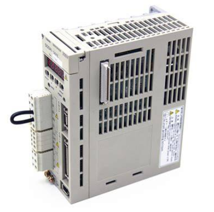
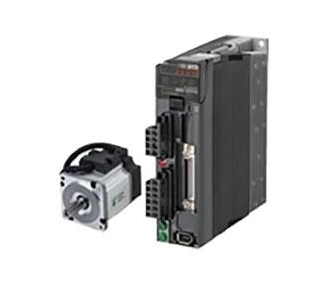
 Omron R7D-APA3H 30W Servo Drive
 -
 Giddings Lewis 502-03638-41R3 PLC Processor
 -
 Omron SCY-P1 Sequencer Controller
 -
 Siemens C98043-A7002-L1-13 PCB Board
 -
 SACS TECNICA Palletizer PC PLC Control System
 -
 AutomationDirect T1F-14THM PLC Module T1F14THM
 -
 OMRON C200H-AD003 Analog Input Unit PLC Module
 -
 Applied Materials 0010-A0000 Electricity Box PLC 200mm
 -
 ABB RVT-6 Power Factor Controller RVT6
 -
 Allen-Bradley 2094-BC01-MP5-M Kinetix 6000 Axis Module
 -
 OMRON FQM1S-MC233 Motion Controller PLC Module
 -
 OMRON C200H-SNT31 PLC Special I-O Module
 -
 Yaskawa SGMPH-04AAA61D-OY Servo Motor 400W 200V
 -
 Yaskawa SGMGH-09DCA6F-OY AC Servo Motor 850W 400V
 -
 REFU ELEKTRONIK SR17002 PLC Logic Module Circuit Board
 -
 Siemens 6DP1231-7AA PLC Board Module Industrial Control
 -
 ABB SACE ISOMAX S3 N 160 Molded Case Circuit Breaker
 -
 OMRON C120-SC024-V1 SYSMAC C120 Compact PLC Unit
 -
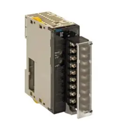
 OMRON CJ1W-SCU41-V1 Serial Communication Unit PLC Module
 -
 OMRON 3G3MX2-A4110-ZV1 MX2 Variable Frequency Drive
 -
 Yaskawa SGDH-04AE-OY Sigma-II Servo Driver 400W 200V
 -
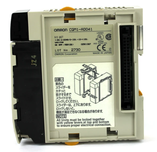 OMRON CQM1-AD041 Analog Input Module PLC I/O Unit
 -
 Delta Omega XML2-0060-45-4/S-A Servo Drive
 -
 Omron CJ1W-AD041 Analog Input
 -
 Omron CJ1W-NC271 Position Control Unit
 -
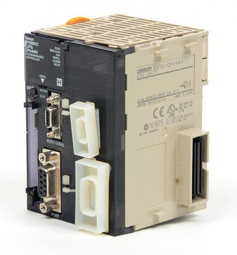 Omron CJ1G-CPU45H PLC CPU
 -
 Omron CJ1W-EIP21 EtherNet/IP Unit
 -
 Omron F210-C15 Vision Mate Controller
 -
 Omron CQM1H-ADB21 Analog I/O Board
 -
 Omron GRT1-PRT PROFIBUS DP-V1 Adapter
 -
 Omron CP1H-Y20DT-D PLC CPU
 -
 TE.CO TFX 4G 1.5 Grey Cable 470m
 -
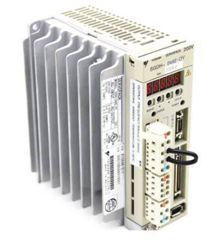 Yaskawa SGDH-04AE-OY Servo Driver 400W 200V
 -
 OMRON CJ1H-CPU66H V4.0 PLC CPU
 -
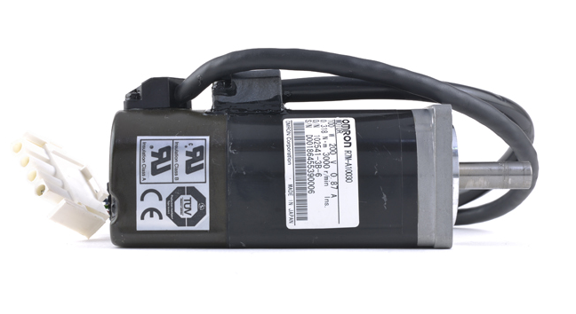 OMRON R7M-A10030-BS1 Servo Motor 200W 100V
 -
 OMRON FQM1-MMA21 Motion Controller
 -
 Yaskawa SJDE-08APA Servo Amplifier
 -
 OMRON CQM1-AD041 Analog Input Unit
 -
 Siemens OCI55 Dialogue Module Landis
 -
 OMRON F350-C10E Image Processing Unit
 -
 OMRON NT10S-SF121 HMI Terminal
 -
 SIEMENS 3RB1262-0LB31 Overload Relay
 -
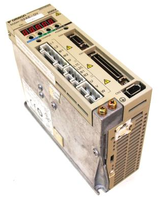
 OMRON YASKAWA SGDS-02A12A Servo Drive
 -
 TE.CO TFX 4G 1.5 Grey Cable ST 500m
 -
 FANUC A16B-3200-0362 PCB Control Board
 -
OMRON CQM1-ARM21 Analog Output Unit
-
 Allen-Bradley 1788-EN2DN Ethernet DeviceNet Gateway
 -
 Siemens 3VL9440-7EE40 3VL4740-2AA46-0AA0 Circuit Breaker
 -
 OMRON CJ1W-AD041-V1 Analog Input Unit
 -
 OMRON CQM1-AD041 CQM1-IPS02 Analog Input Power Supply
 -
 Texas Instruments System 505 PLC 525-110 525-1102
 -
 OMRON CQM1-AD042 Analog Input Unit
 -
 Yaskawa SGDH-04AE-OY Servo Driver 200V 400W
 -
 CTI 2512 75W Power Supply for CTI 2500
 -
 Omron F300-B5 Image Processing Unit
 -
 Mitsubishi 15050-PR01A PLC Board
 -
 Omron CQM1-TC101 Temperature Controller
 -
 SCE M68-2000 2 Axis Motion Controller HW 2.3/B
 -
 Omron 3Z4SP-C22 Visual Positioning Sensor
 -
 Omron 3G3SV-BB007-E 0.75kW VFD
 -
 CML 6622 IRD Entek AW10528 Vibration Monitor
 -
 Omron CP1L-EL20DR-D PLC CPU
 -
 TE.CO TFX 4G 1.5 Grey Cable 500m
 -
 Mitsubishi Electric 3BK23057 Circuit Board Module
 -
 OMRON FQM1-MMP21 Motion Control Module
 -
 OMRON CP1E-E40SDR-A Micro PLC CPU Unit
 -
 KEBA CU201 PLC Control Unit
 -
 OMRON F150-C10E-2 Vision Sensor Controller
 -
 YASKAWA SGDH-04AE-OY Sigma-II Servo Driver
 -
 OMRON CS1H-CPU65-V1 PLC Central Processing Unit
 -
 OMRON NB7W-TX01B Interactive Display HMI
 -
 OMRON C500-TU002E Programmable Logic Controller Timer Unit
 -
 OMRON C200HW-PRT21 PROFIBUS DP Slave Unit
 -
 ExcelTech MX-5-S-I-6-4 Static Transfer Switch
 -
 Allen-Bradley 100-B300ND3 Contactor 304A 600V
 -
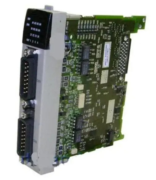
 Pasaban MTC-3052 Fast I/O PLC Card
 -
 OMRON CQM1-TC101 Temperature Control Unit
 -
 OMRON 3G3SV-BB007-E VFD 0.75kW 220V
 -
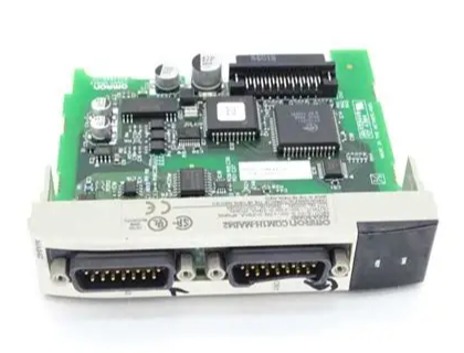 OMRON CQM1H-MAB42 PLC Module
 -
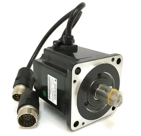
 OMRON R88M-K75030T-S2 Servo Motor
 -
 Yaskawa SGMAH-03DAAA61 Servo Motor 200V 300W
 -
 OMRON F300-P Power Supply Unit
 -
 Land System 4 M1 Thermometer 65071800C-L35-A50
 -
 Yamatake MAH10-ME0100 ME-NET Module
 -
 Siemens Simatic 505 16 Slot PLC Rack
 -
 Yaskawa SGDH-02AE-OY Servo Driver 200W
 -
 SCE M68-2000 2-Axis Motion Controller
 -
 Zenith Controls K-1201 Transfer Switch Controller
 -
 Yaskawa SGDH-02AE-OY 200W Servo Driver
 -
 Yaskawa SGMAH-02AAA61D-0Y 200W Servo Motor
 -
 Schneider TSX P573634M Modicon Premium CPU
 -
 Siemens 6FX5002-5DN31-1DA0 Power Cable
 -
 Omron CJ1G-CPU43H CPU Unit 30K Steps
 -
 OMRON C28P-EDR-D PLC Unit
 -
 SIEMENS S7-300 PLC System
 -
 Schneider TP400-PLC-1411 Board
 -
 Siemens 6FC5203-0AF00-0AA3 Panel
 -
 ALLEN BRADLEY 1754-L28BBB GuardPLC
 -
 Omron E6C3-AG5B-C Encoder
 -
 SCE M68-2000/5 CNC Controller
 -
 SCHNEIDER TM2ALM3LT Module
 -
 OMRON C200H-OV001 Voice Module
 -
 OMRON R88M-H30030 Servo Motor
 -
 Bosch RD500 Indramat Servo Drive RD51.2-4B
 -
 Siemens 6SE7090-0XX84-0AH2 T300 Module
 -
 Omron GRT1-TS2P SmartSlice Thermocouple Input
 -
 Xaar XP55500016 XUSB Drive Electronics
 -
 Siemens 6SL3210-1SE21-8UA0 PM340 Power Module
 -
 Mitsubishi GT2708-VTBA Touch Display 8.4 Inch
 -
 Pasaban Fast I/O MTC-3052 PLC Card
 -
 ABB ACS355-01U-02A4-2 VFD 0.37kW
 -
 Yamatake MAH20-PC2100 Processor Module
 -
 Allen Bradley 1774-P1 PLC Power Supply
 -
 Yaskawa SGDH-04AE-OY 400W Servo Driver
 -
 Omron CPH-X40DT1-D PLC CPU Unit
 -
 Pilz PNOZ mm0.2p Safety PLC Mini 772002
 -
 Siemens 6SL3555-OPR01-0AA0 Sinamics G110M Panel
 -
 Sanyo PLC-XTC50L LCD Projector
 -
 SCE M68-2000 2-Axis Motion Controller
 -
 Omron CS1W-CT021 High-Speed Counter Unit


