
Horner APG HE693CALKIT simulation module
Horner APG HE693CALKIT calibration software is a computer program designed to support on-site and factory calibration of specific Horner APG simulation modules.
(2) Package composition
Each set includes: a floppy disk with calibration software, an RS-232 9-pin serial cable, a TTL to RS-232 converter, and an RS-232 ribbon cable with a 10 pin plug.
(3) Software operation requirements
Operating environment: Requires running on an IBM or compatible computer using DOS 3.1 or higher.
Hardware requirements: A text display is required and a serial port (COM1 or COM2) is used. The program defaults to using COM1.
(4) Module connection and preparation
The simulation module needs to be connected to the selected serial port on the computer through an RS-232 cable, combined with a TTL-to-RS-232 converter or an RS-232 ribbon cable with a 10 pin plug (depending on the simulation module to be calibrated).
The module does not need to be configured in the PLC, but appropriate power must be provided for the bus pins of the module.
Horner APG HE693CALKIT simulation module
Product Introduction
(1) Product Features
Horner APG HE693CALKIT calibration software is a computer program designed to support on-site and factory calibration of specific Horner APG simulation modules.
(2) Package composition
Each set includes: a floppy disk with calibration software, an RS-232 9-pin serial cable, a TTL to RS-232 converter, and an RS-232 ribbon cable with a 10 pin plug.
(3) Software operation requirements
Operating environment: Requires running on an IBM or compatible computer using DOS 3.1 or higher.
Hardware requirements: A text display is required and a serial port (COM1 or COM2) is used. The program defaults to using COM1.
(4) Module connection and preparation
The simulation module needs to be connected to the selected serial port on the computer through an RS-232 cable, combined with a TTL-to-RS-232 converter or an RS-232 ribbon cable with a 10 pin plug (depending on the simulation module to be calibrated).
The module does not need to be configured in the PLC, but appropriate power must be provided for the bus pins of the module.
Set conditions
(1) General Requirements (2.1)
Module installation: The module to be calibrated must be inserted into the PLC it will be used in the application; When inserting, the PLC must be powered off. After the module is correctly inserted into the PLC rack, the rack should be installed vertically (see Figure 1) to ensure good ventilation of the module; The PLC must be in 'stop' mode.
Stabilization time: After inserting the module into the PLC and completing the calibration connection, it needs to stabilize for at least 15 minutes after power on to ensure appropriate temperature balance.
Environmental requirements: Do not expose any equipment involved in the module or calibration process to extreme temperature changes; Calibration can be performed using an expansion rack.
(2) Set up process (2.2)
No additional special steps are required, and it should be carried out in conjunction with equipment preparation and module specific conditions.
(3) Equipment Requirements (2.3)
Calibrator: High quality calibrators (such as Omega CL511) must be used, and their accuracy must be more than twice that of the module (for example, THM884 has an accuracy of ± 1 degree Celsius, and the calibrator accuracy must be at least ± 0.5 degrees Celsius); It is recommended that all Horner Electric simulation modules use battery powered calibrators. When calibrating any thermocouple module, a battery powered calibrator must be used.
Wire requirements: The wire used for calibration must be the same as the wire used in the application, and must be of high quality with the shortest possible length; Avoid exposing wires to excessive radio frequency (RF) or electromagnetic interference (EMI) during the calibration process to prevent introducing errors.
(4) Module specific conditions (2.4)
1. Analog input module (2.4.1)
Covering HE693ADC406, HE693ADC405, HE693ADC415, HE693ADC410, HE693ADC420, the general requirements are as follows:
Calibrator: More than twice the accuracy of the module and powered by batteries.
Wire: Use high-quality wire that is the same as the wire used in the application and has the shortest length.
Environment: Avoid exposing the module to excessive EMI or RF, extreme temperature changes.
Installation and status: The module needs to be inserted into the PLC slot used in the application, and after being powered on and connected, it should be stable for at least 15 minutes. It should be installed vertically (in the panel installation position), and the PLC should be in "stop" mode; The unused channels during the calibration process of HE693ADC406 need to be short circuited and grounded.
2. Analog output module (2.4.2)
Regarding HE693DAC410 and HE693DAC420, it is required to be consistent with the analog input module (except for the channel short-circuit grounding of HE693ADC406).
3. Resistance Temperature Detector (RTD) module (2.4.3)
Including HE693RTD600, HE693RTD601, HE693RTD660, HE693RTD665, HE693RTD666, in addition to meeting the general requirements of the analog input module, there are additional requirements: unused channels during calibration must be short circuited and grounded; Modules with a suffix of -20 need to use the a=d switch (PT100D) in the calibration software.
4. Strain gauge module (2.4.4)
Including HE693STG883 and HE693STG884, it is required to be consistent with the RTD module (without using channel short-circuit grounding).
5. Thermocouple module (2.4.5)
Covering multiple models such as HE697THM160 and HE693THM166, in addition to meeting the general requirements for analog input modules, there are additional requirements: modules with a suffix of -21 need to use external ISOBLK for cold end compensation; During the calibration process, the last channel needs to be short circuited and grounded to optimize cold end compensation; Modules with suffix -02 need to use the "=k" switch in the executable file (refer to section 4.1).

Calibration process
(1) General Instructions (3.1)
The general calibration process is only a basic framework, with slight differences in the calibration process of each module, but the core logic is consistent. The simulation module needs to be calibrated according to the specific process described in the subsequent sections; Table 3.1 lists the simulation modules and their corresponding calibration files, with some corresponding relationships as follows:
Product model calibration software Product model calibration software
HE693ADC405 adc4x5.exe HE693THM166 thm166.exe
HE693ADC410、HE693ADC420 adciso.exe HE693THM665、HE693THM666、HE693THM668 thm668.exe
HE693ADC406 adc406.exe HE693THM884(REV. A,B,C) thm884_1.exe
HE693DAC410、HE693DAC420 daciso.exe HE693THM884(REV. D,E,F,G,H,HX,J,K,L) thm884_2.exe、THM884cal.exe(Windows Version)
(2) Software startup (3.2)
1. Startup steps
Select the corresponding executable file from the floppy disk list (for example, calibrate HE693THM884 and select Thm884. exe).
Enter the corresponding command at the DOS prompt to run the calibration program: when using the COM1 port by default, enter "Thm884" and press "ENTER"; When using the COM2 port, enter "Thm884=C2" and press "ENTER".
To view command line switches and their instructions, enter "Thm884=?" at the DOS prompt and press "ENTER".
2. Screen Example (3.2.1)
After the program starts, the top of the screen will display the program name and version. Taking the THM884 thermocouple module calibrator (V2.04) as an example, the screen will display channel values, types, scales, zero points, and other information, as well as module models, channel quantities, hardware alarms, versions, and other parameters. At the same time, it will prompt the functions of each function key (F1-F9, Esc) (such as F1 calibration of J-type thermocouples, Esc exit, etc.).
3. Windows version software installation and operation (3.2.2, 3.2.3)
Installation: Load the floppy disk containing the THM884cal.exe (Windows version) installation file, locate and select the setup. exe file, follow the prompts to select the application file storage directory, and after installation is complete, you can use it.
Run: Find THM884cal.exe in the directory specified during installation, double-click the file to open the application; This version operates similarly to the DOS version. If you have any questions about the functionality, press the F12 key to access the help file.
(3) Process Overview (3.3)
Disable non-volatile random access memory (NVRAM): If the "disable" option is not provided, it will be automatically disabled. This step closes the old calibration constant and uses the default value for new calibration. The module needs to be reset to use the default value.
Disable PLC configuration: Make the module use default values (the module defaults to PLC configuration mode when powered on).
Initialization module: Execute after disabling PLC configuration.
Perform calibration: If it is a thermocouple module, you need to first select the calibration type. The software will prompt you for each step in the calibration process, and you need to follow the prompts.
Update NVRAM: Update the new default values to NVRAM.
Activate NVRAM: Enable the module to use the stored calibration constants the next time it is powered on.
Re initialize the module: Let the module re read the calibration and filtering constants from the NVRAM.
(4) Module specific calibration process (3.4)
The calibration steps and corresponding function keys for each module are as follows (some module examples):
1. Analog input module (3.4.1)
Taking HE693ADC406, HE693ADC405/415, and HE693ADC410/420 as examples:
Step Process Function Key
1. Disable NVRAM F5
Initialization module F6
3. Disable PLC configuration F8
Perform calibration (follow software prompts) F1
5 Update NVRAM (store new constants, select "Yes") F3
Activate NVRAM F4
7 Initialization module F6
2. Analog output module (3.4.2)
The calibration steps for HE693DAC410 and HE693DAC420 are the same as those for the analog input module. It should be noted that when calibrating the analog output module, the PLC must be in non operating mode.
3. RTD module (3.4.3)
HE693RTD600 and other models:
Step Process Function Key
1. Disable NVRAM F7
Initialization module F6
3. Disable PLC configuration F8
Perform calibration (follow software prompts) F1, F2, F3
5. Update NVRAM (store new constants, select "Yes") F5
Activate NVRAM F7
7 Initialization module F6
4. Strain gauge module (3.4.4)
The calibration steps for HE693STG883 and HE693STG884 are the same as those for the analog input module.
5. Thermocouple module (3.4.5-3.4.7)
HE697THM160, HE697THM260: Follow the same steps as the RTD module.
HE693THM166: The steps are consistent with the analog input module.
HE693THM406 and other models: The steps are consistent with the RTD module.
HE693THM884 (K-type+channel offset calibration): Use THM884_K.bat batch file, consisting of 15 steps, including module installation, power on, NVRAM disable/activate, PLC configuration disable/enable, calibration execution, offset setting and transmission, NVRAM update, module initialization, etc. Some steps require the use of function keys such as F1, F4, F5, F6, F7, F8, and finally remove the module after power off.
HE693THM894 (K-type calibration): Use the THM894_K.bat batch file, following the same steps as HE693THM884 (K-type+channel offset calibration).
Switch settings
(1) Switch Description (4.1)
Many simulation modules can be temporarily configured and software switches can be used, such as observing the reaction of thermocouple modules using T-shaped thermocouple wires (rather than the commonly used J, E, R types); Please note that the=T,=K, and=C switches are volatile and will not cause permanent changes to the module, while commands such as=NVRAM (such as=S) will cause permanent changes. The switch format is "Thm884 [=C1] [=C2] [=T] [=K] [=Snnnn. n, nnnn. n, nnnn. n,...]", and the functions of each switch are as follows:
Switch Function Description
=C is used to select serial ports, for example=C1 (COM1),=C2 (COM2)
=T represents test mode, still transmitting command messages, but variables use internal values, receiving messages generated by simulation (software simulation mode), without the need to connect modules
=K sets the calibration type to K instead of the default J type
=Set calibration scale points for S, separated by commas (without spaces), in the order of K (or J) median, K high value, E median, E high value, R median, and R high value; When the value is 0, use the default value; If there are less than 6 entries, the remaining entries will use default values; The scale point must not be lower than 25 degrees Celsius (this low-temperature calibration point is crucial for optimizing cold end compensation)
(2) Example (4.2)
Command function
Thm884=C1 specifies COM1 as the serial port (default port)
Thm884=C2 specifies COM2 as the serial port (this command needs to be called to use COM2)
Thm884=T Enable test mode, transmit commands but only simulate messages, do not store values
Thm884=K sets the calibration type to K type (default J type), suitable for special applications and European calibration
Thm884 =S600.0,700
- OMRON
- ABB
- General Electric
- EMERSON
- Honeywell
- HIMA
- ALSTOM
- Rolls-Royce
- MOTOROLA
- Rockwell
- Siemens
- Woodward
- YOKOGAWA
- FOXBORO
- KOLLMORGEN
- MOOG
- KB
- YAMAHA
- BENDER
- TEKTRONIX
- Westinghouse
- AMAT
- AB
- XYCOM
- Yaskawa
- B&R
- Schneider
- KONGSBERG
- NI
- WATLOW
- ProSoft
- SEW
- ADVANCED
- Reliance
- TRICONEX
- METSO
- MAN
- Advantest
- STUDER
- DANAHER MOTION
- Bently
- Galil
- EATON
- MOLEX
- DEIF
- B&W
- ZYGO
- Aerotech
- DANFOSS
- Beijer
- Moxa
- Rexroth
- Johnson
- WAGO
- TOSHIBA
- BMCM
- SMC
- HITACHI
- HIRSCHMANN
- Application field
- XP POWER
- CTI
- TRICON
- STOBER
- Thinklogical
- Horner Automation
- Meggitt
- Fanuc
- Baldor
- SHINKAWA
- Other Brands
- UniOP
- KUKA
- Iba
-
 LTi SO84.450 Servo Drive Controller - 450A Three-Phase BG7
 -
 LTi SO84.375 Servo Drive Controller - 375A Three-Phase BG7
 -
 LTi SO84.325 Servo Drive Controller - 325A Three-Phase BG7
 -
 LTi SO84.250 Servo Drive Controller - 250A Three-Phase BG7
 -
 LTi SO84.170 Servo Drive Controller - 170A Three-Phase BG6a
 -
 LTi SO84.143 Servo Drive Controller - 143A Three-Phase BG6a
 -
 LTi SO84.110 Servo Drive Controller - 110A Three-Phase BG6
 -
 LTi SO84.090 Servo Drive Controller - 90A Three-Phase BG6
 -
 LTi SO84.072 Servo Drive Controller - 72A Three-Phase BG5
 -
 LTi SO84.060 Servo Drive Controller - 60A Three-Phase BG5
 -
 LTi SO84.045 Servo Drive Controller - 45A Three-Phase BG5
 -
 LTi SO84.032 Servo Drive Controller - 32A Three-Phase BG4
 -
 LTi SO84.024 Servo Drive Controller - 24A Three-Phase BG4
 -
 LTi SO84.020 Servo Drive Controller - 20A Three-Phase BG3
 -
 LTi SO84.016 Servo Drive Controller - 16A Three-Phase BG3
 -
 LTi SO84.012 Servo Drive Controller - 12A Three-Phase BG2
 -
 LTi SO84.008 Servo Drive Controller - 8A Three-Phase BG2
 -
 LTi SO84.006 Servo Drive Controller - Three-Phase 230-480V 6A
 -
 LTi SO84.004 Servo Drive Controller - Three-Phase 230-480V 4A
 -
 LTi SO82.004 Servo Drive Controller - Single-Phase 230V 4A
 -
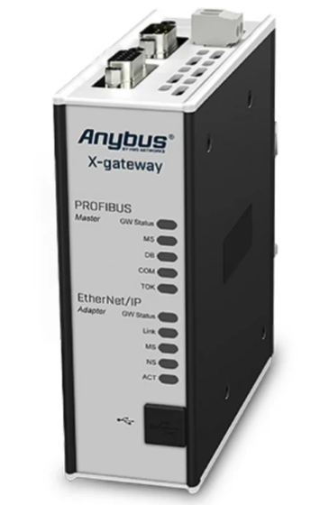 HMS Anybus AB7646-F Gateway Manual
 -
 Schneider ATV930D75N4 Inverter Manual
 -
 Mitsubishi Q2ASHCPU-S1 System Manual
 -
 Fanuc A20B-3300-0319 Board Specification
 -
 Mitsubishi QD60P8-G Counter Module Guide
 -
 Nidec Unidrive M701 Inverter Manual
 -
 ABB AO895 Analog Output Module Guide
 -
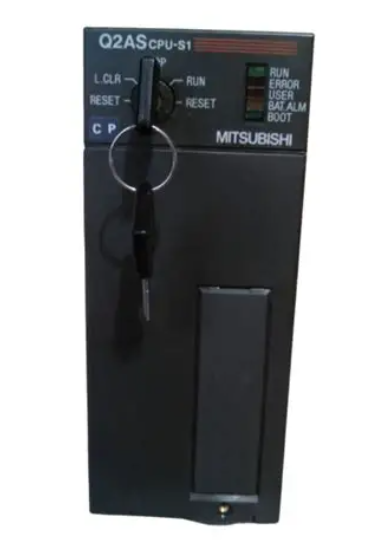 Mitsubishi Q2ASHCPU Controller System Manual
 -
 ABB Pluto S20 v2 Safety PLC Manual
 -
 Omron CJ1W-NC413 Position Module Manual
 -
 B&R X20AI4632 Analog Input Module 4 Channel
 -
 OMRON CS1G-CPU44H Ver. 4.1 CPU Unit PLC
 -
 Beckhoff EL2911-2200 TwinSAFE Logic Terminal for EtherCAT
 -
 Mitsubishi 2D-TZ368 Parallel I/O Interface Card
 -
 Mitsubishi A3ACPU PLC CPU Module for MELSEC A Series
 -
 Mitsubishi NF630-SEW 4P Adjustable Circuit Breaker 300-630A
 -
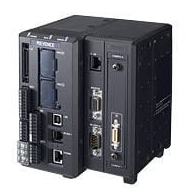 Keyence XG-8700L Multi-camera Vision System for Inspection
 -
 Beckhoff C6017-0010 Ultra Compact Industrial PC
 -
 B&R 3AT660.6 PLC Module from Automation Panel Series
 -
 GE F31X300CCHALG2 PC Board with 531X133PRUAPG1 Card
 -
 STMicroelectronics STM32L100R8T6ATR MCU Arm Cortex-M3
 -
 Omron CS1W-CLK13 Controller Link Unit
 -
 Schneider BMENOC0301 Ethernet Communication Module
 -
 HELUKABEL Braids PLC-30 40 E2UK Braided Cable Sleeve
 -
 Pe323 h0102de323a0 PLC I/O Module
 -
 Mitsubishi GT2512-STBA GT2512-STBD HMI 12.1 Inch Touch Screen
 -
 Samsung LTM213UP01 21.3 Inch LCD Monitor Panel
 -
 Allen-Bradley 440R-W23219 Guardmaster Safety Relay
 -
 Beckhoff EL2535 EtherCAT Terminal PWM Output
 -
 HELUKABEL Braids PLC-40 55 E2UK Braided Cable Sleeve
 -
 Allen Bradley 1769-OB16 16-Point Sourcing Output Module
 -
 Balluff BES 516-604-DZ-3 Delay Safety Relay for Industrial Timing
 -
 Siemens 6GK7542-1AX10-0XE0 PROFIBUS Communication Module for S7-1500
 -
 GE IC693BEM340 FIP Controller for Series 90-30 PLC
 -
 OMRON C200HG-CPU63-E Programmable Logic Controller CPU Unit
 -
 Schneider EOCR-PMZ Relay Manual
 -
 Honeywell C36TC0UA21D0 Controller Specifications
 -
 Emerson Ovation VE4001S2T2B4 Input Module
 -
 Omron CJ1M-CPU22 CPU Specifications
 -
 Grundig NEA02 AES 0 Card Specifications
 -
 Omron CJ1W-AD081-V1 Analog Input Specifications
 -
 IDEC FS1A-C21S Safety Controller Manual
 -
 IFM O3D303 Smart 3D Sensor Specifications
 -
 Siemens 6SN1123-1AB00-0BA2 Power Module Guide
 -
 B&R 4PP035.0300-01 Power Panel Manual
 -
 Siemens 6ES7 153-2BA10-0XB0 IM Module
 -
 Beckhoff EL3356-0010 Analog Input Module
 -
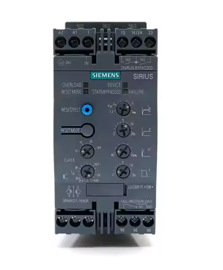 Siemens 3RW4037-1BB04 Soft Starter
 -
 Lenze EVF8216-E VFD
 -
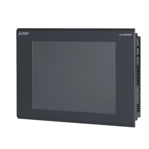 Mitsubishi GT2310-VTBA GT2310-VTBD HMI
 -
 Allen-Bradley 1764-28BXB PLC MicroLogix 1500
 -
 SP-RDM2 Relay Module Dual Reader Interface
 -
 Keyence GC-S84 Programmable Safety Controller
 -
 Mitsubishi GT2310-VTBA GT2310-VTBD HMI 10.4 Inch
 -
 Eurotherm MINI8 PLC Temperature Controller
 -
Mitsubishi GT2512-STBA GT2512-STBD HMI 12.1 Inch
-
 ABB ACS380-040S-02A6-4 VFD 0.75kW 480V
 -
 Dage PC514 ISSUE A PLC O.P.I Board
 -
 ROBICON 460T46.01 REV C Printed Circuit Board
 -
 Omron NX502-1300 Controller Unit NX5 CPU
 -
 B&R X20CM0985 PLC Module
 -
 Banner XS26-2DE 85064 Safety Controller
 -
 Siemens 3SK2122-1AA10 Safety Relay
 -
 HMS Anybus AB7646-F Gateway PROFIBUS EtherNet/IP
 -
 Siemens 6SN1118-0DM11-0AA0 SIMODRIVE 611 Card
 -
 Siemens C98043-A7001-L2-4 CUD1 Control Board
 -
 Stein Sohn E 083.1 PLC Rack Module 0010026-054100A
 -
 Allen Bradley 800H-2HA7P Push Button Station
 -
 Schneider BMXNRP0200 M340 PLC Module
 -
 KEPCO BOP 200-1M Bipolar Power Supply Amplifier
 -
 Mitsubishi Q2ASHCPU PLC Module with A1SX42 A1SY42 QC24-R2 A1SD75P2-S3
 -
 Siemens Siprotec 7SJ61 Overcurrent Protection
 -
 Keyence LJ-V7000 Controller Laser Profiler
 -
 Siemens 6EP3437-8SB00-0AY0 Power Supply 20A
 -
 Pasaban MC-2006 03 CAN Bus PLC Card
 -
 ETAS ES600.2 PLC Module Prototyping
 -
 ABB ACS800-01-0005-3+P901 Frequency Converter
 -
 Omron NX102-1100 PLC Module Machine Automation
 -
 Square D BMXCPS3500 PLC Power Supply Module
 -
 Allen-Bradley 96657704 Fiber Optic Converter 1771-AF
 -
 Corcom 20VK1 Power Line Filter
 -
 Novellus 2805-11407 PLC Rack Assembly
 -
 Sick RLY3-EMSS100 Safety Relay Module
 -
 Microchip PIC12F508-I/P Microcontroller
 -
 Fanuc A02B-0098-B511 Motherboard
 -
 Merlin Gerin PB80 PLC Rack Module
 -
 ABB Pluto S20 V2 CFS Safety PLC
 -
 Honeywell TK-PRR021 Redundancy Module
 -
 B&R 7XX419L.50-1 Bus Controller
 -
 Mitsubishi NV400-SW 3P 300A Breaker
 -
 B&R X20AT2222 Temperature Module
 -
 Corcom 20VK1 EMI RFI Filter
 -
 Novellus 2805-11407 PLC Rack Assy
 -
 Mitsubishi FXAOM01BD Analog Output Module 4CH
 -
 NORIS A1-91 PCB Rack Module A1-91-4 A1-91-5 A1-91-6 A1-91-7 A1-91-8
 -
 Omron ZFV-SC50 Smart Camera Vision Sensor
 -
 Schneider Electric EOCR-PMZ Motor Protection Relay
 -
 B&R X20 SO 6300 PLC Module Safety Output
 -
 Mitsubishi A2ACPU21-S1 CPU Module MELSEC
 -
 Siemens 6ES7405-0KA02-0AA0 PS405 10A Power Supply
 -
 Samsung PVU-2424 Power Supply Unit DC24V 24W
 -
 ATTO controlSYS ATT0-CPU44 PLC with Display
 -
 Lenze EPZ-10203 CANPT010W3E Absolute Encoder
 -
 GE IS215WEMAH1A+IS210BPPBH2CAA Mark VIe Embedded Processor and Backplane Power Distribution Board
 -
 GE IS215AEPAH1CH+IS210BPPBH2CAA Mark VIe Application Processor and Backplane Power Distribution Board
 -
 GE IS215WECAH1B+IS210BPPBH2CAA Mark VIe Control Platform
 -
 GE PCM Regulator for EX2100e Power Conversion Module 151X1235DB15SA1
 -
 Lenze ECSEA048C4B servo drive


