
Thinklogical Velocity KVM-34 series KVM fiber extender
Thinklogical Velocity KVM-34 series KVM fiber extender
Product positioning and core values
1. Product positioning
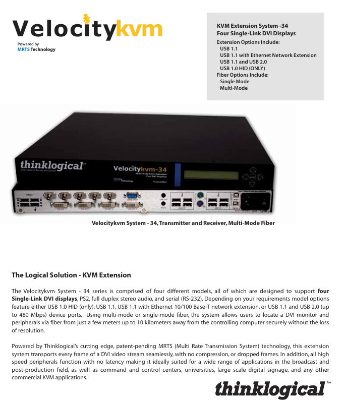
The Velocitykvm-34 series is a four screen single link DVI KVM fiber optic extension system that uses a "transmitter receiver" architecture to achieve remote separation and control of computers and peripherals through single-mode/multi-mode fibers. It supports video, audio USB、 The synchronous transmission of multiple signals through serial ports solves the three major pain points of "long-distance signal attenuation, high-resolution uncompressed transmission, and compatibility with multiple peripherals".
2. Core values
Uncompressed high-definition transmission: relying on patented MRTS (Multi Rate Transmission System) technology, 6.25Gbps bandwidth supports all single link DVI resolutions (such as 1920 × 1080) 1200@60Hz )No frame loss, no compression, zero image delay;
Ultra long distance coverage: Single mode fiber can transmit up to 10km, and multimode fiber (OM3 enhanced type) can transmit up to 1000m, meeting the deployment needs of large parks, cross buildings, and other long-distance environments;
Multi interface compatibility: integrated with USB (HID/1.1/2.0), PS2, RS-232 serial port, bidirectional stereo audio, compatible with keyboards, mice, USB drives, high-speed storage devices, microphones and other peripherals;
High security: Provides "HID only" models (with USB storage devices disabled) to meet the security control needs of classified scenarios such as command centers and financial data centers.
Product classification and core differences
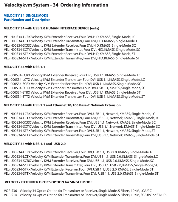
The series includes four core models, all of which support four screen DVI output, PS2, RS-232 serial port, and bidirectional audio. The core difference lies in USB function and network expansion capability. The specific classifications are as follows:
Model Type Core Interface Configuration Transmission Rate Applicable Scenarios
USB 1.0 HID (only) supports USB ergonomic devices (keyboard, mouse, drawing board), disabled USB storage - classified scenarios (such as military command center, financial data center), to prevent data leakage
USB 1.1 supports USB 1.1 full speed peripherals (USB flash drives, tablets, low-speed printers) at 12Mbps for regular office scenarios, without the need for high-speed USB devices
USB 1.1+Ethernet (10/100Base-T) USB 1.1 functionality+Ethernet expansion, capable of transmitting network signals via fiber optic USB 12Mbps; Ethernet 100Mbps requires simultaneous extension of network and KVM signals in scenarios such as remote laboratories and distributed offices
USB 1.1+USB 2.0 compatible with USB 1.1 (low-speed) and USB 2.0 (high-speed) devices. USB 2.0 can reach 480Mbps and requires high-speed peripherals, such as DVD drives, high-speed portable hard drives, and professional scanners
In addition, all models offer single-mode/multi-mode fiber options, and fiber connectors support LC, SC, and ST types to adapt to different fiber infrastructure.
Key technical parameters
1. Transmission performance parameters
Parameter category specification details
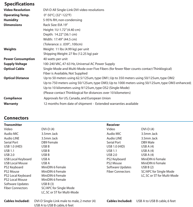
Video signal single link DVI-D, supporting all resolutions (such as 1920 × 1080) 1080@60Hz 1920 × 1200@60Hz )
Transmission bandwidth of 6.25Gbps (MRTS technology), no compression, no frame loss
Fiber optic distance - multimode: OM1 (62.5/125 μ m) 50m; OM2(50/125μm)350m; OM3(50/125μm)750m; OM3 Enhanced 1000m
-Single mode: OS2 (9/125 μ m) 10km (for distances exceeding 10km, please contact the manufacturer for customization)
The standard number of optical fibers is 5 cores (4 cores for video/USB, 1 core for USB/DC feedback), supporting customized models with fewer cores
2. Physical and environmental parameters
Parameter category specification details
Size 19 inch rack mount (EIA standard), 1U height (4.40cm), width 44.5cm, depth 36.1cm
The weight of a single machine is 11lbs (4.99kg), and the transportation weight of the transmitter+receiver set is 27lbs (12.25kg)
Power supply wide voltage 100-240V AC (47-63Hz), single machine power consumption 40W
Working environment temperature 0-50 ℃ (32-122 ℉), humidity 5% -95% RH (non condensing)
Certified to comply with electrical safety standards in the United States, Canada, and the European Union (such as CE, FCC, cUL)
12 months warranty (expandable extended warranty)
3. Interface configuration (transmitter vs receiver)
Equipment interface type and quantity remarks
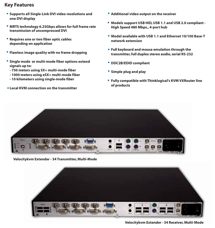
Transmitter - Video: DVI-D (4, connected to computer)
-USB: USB B (HID/1.1/2.0, depending on model), local USB A (keyboard/mouse, 2)
-PS2: MiniDIN 6 female head (keyboard/mouse, 1 each; local 1 each)
-Audio: 3.5mm interface (1 microphone, 1 line input)
-Serial port: DB9 female head (RS-232)
-Fiber optic: LC/SC/ST (single-mode SC/APC, multi-mode LC/SC/ST)
-Software upgrade: USB B (3) local interfaces support "near end control", which means that the computer can be directly operated with a keyboard and mouse
Receiver - Video: DVI-D (4, connected to monitor)
-USB: USB A (4, connected to peripherals)
-PS2: MiniDIN 6 female head (keyboard/mouse, 1 each)
-Audio: 3.5mm interface (1 microphone, 1 line output)
-Serial port: DB9 male (RS-232)
-Fiber optic: Same transmitter
-Software upgrade: USB B (2) supports bidirectional audio transmission, enabling sound synchronization between the near end microphone and the far end speaker
System architecture and deployment specifications
1. Core architecture
Adopting a "point-to-point" fiber optic transmission architecture, the signal flow direction is as follows:
Signal acquisition: The transmitter is connected to a computer to collect DVI video, USB/PS2 (keyboard and mouse), audio, and serial port signals;
Fiber optic transmission: The signal is transmitted uncompressed to the receiver through a 5-core fiber optic cable (single-mode/multi-mode optional);
Signal output: The receiver is connected to the display and peripherals (keyboard, mouse, USB flash drive, etc.) to restore the signal and drive the peripherals;
Local control: The transmitter is equipped with a local USB/PS2 interface, supporting direct operation from the computer and achieving dual control of "local+remote".
2. Key deployment requirements
Fiber selection: Strictly match single-mode/multi-mode models, prioritize OM3 (50/125 μ m) for multi-mode to extend transmission distance; Fiber optic cables must comply with TIA/EIA standards to avoid signal loss caused by the use of inferior fiber optic cables;
Interface connection: DVI cables require single link shielded cables (factory supplied 2-meter cables), and USB cables should not exceed 6 feet (approximately 1.8 meters) in length to avoid signal attenuation;
EDID/DDC configuration: The transmitter has a built-in universal EDID table and can also read the EDID of the local display; Support "Active DDC" to allow remote displays to provide resolution information feedback to the computer, ensuring display compatibility;
Power isolation: The transmitter and receiver need to be connected to independent power sources to avoid common ground interference (such as sharing sockets with high-power devices).
Selection method and ordering rules
1. Selection process
Confirm transmission distance and fiber type:
Short distance (≤ 1000m): Choose multi-mode model (suffix "M34");
Long distance (≤ 10km): menu model number (suffix "634");
Select interface function:
Confidential scenario: Select "USB 1.0 HID only" (model includes "H00");
Ordinary office: select "USB 1.1" (model includes "000");
Network expansion required: select "USB 1.1+Ethernet" (model includes "N00");
High speed peripheral: select "USB 1.1+2.0" (model includes "U00");
Determine the fiber optic connector:
Small scale deployment: choose LC interface (model including "LC");
Traditional computer room: select SC/ST interface (model includes "SC"/"ST");
Supporting selection: Select fiber optic modules according to requirements (such as VOP-M12 for multimode and VOP-S36 for single-mode).
2. Example of ordering code
Taking "multi-mode, USB 2.0, LC interface receiver" as an example: VEL-U00M34-LCRX
VEL: Product prefix;
U00: Function code (USB 1.1+2.0);
M34: Fiber type (multimode);
LC: connector type;
RX: Device type (receiver, TX is transmitter).
Typical application scenarios
Broadcasting and post production: The studio computer is separated from the control room monitor (500m away), and four DVI videos are transmitted through multi-mode fiber optic cables. USB 2.0 is connected to high-speed storage devices to achieve real-time editing of 4K materials;
Command Center: The server room (remote end) is separated from the command hall (near end) (3km away), with a menu model number and "HID only" configuration. USB storage is disabled to ensure data security, and an RS-232 serial port control switch is extended;
University laboratory: The teacher's computer (teaching building) is connected to the student's experimental equipment (laboratory, 800m away) through multimode fiber optic cable. The USB 1.1+Ethernet model supports extended network and KVM, and students can remotely operate the experimental equipment;
Large digital signage: The central control computer (computer room) in the shopping mall is connected to multiple digital screens (on different floors, at a distance of 300m) through multimode fiber optic cables, and four DVI screens are used to drive screens in different areas, achieving unified content control.
Precautions and maintenance suggestions
Signal interference prevention: Fiber optic cables should be kept away from strong electrical lines (≥ 1m), and USB/audio cables should be avoided from being laid in parallel with power lines to prevent electromagnetic interference from causing image snowflakes and audio noise;
Regular maintenance: Check the cleanliness of fiber optic connectors every quarter (wipe with specialized fiber optic cleaning paper) to avoid signal attenuation caused by dust; Annual testing of power supply voltage stability to prevent voltage fluctuations from damaging equipment;
Troubleshooting: If there is no signal in the video, priority should be given to checking the fiber optic link (using an optical power meter to measure light attenuation); When there is no response from the USB peripheral, confirm whether the model supports the device (e.g. "HID only" model does not support USB drives);
Software upgrade: Upgrade firmware through the USB B interface of the transmitter/receiver, and do not turn off the power during the upgrade process to avoid device damage.
- OMRON
- ABB
- General Electric
- EMERSON
- Honeywell
- HIMA
- ALSTOM
- Rolls-Royce
- MOTOROLA
- Rockwell
- Siemens
- Woodward
- YOKOGAWA
- FOXBORO
- KOLLMORGEN
- MOOG
- KB
- YAMAHA
- BENDER
- TEKTRONIX
- Westinghouse
- AMAT
- AB
- XYCOM
- Yaskawa
- B&R
- Schneider
- KONGSBERG
- NI
- WATLOW
- ProSoft
- SEW
- ADVANCED
- Reliance
- TRICONEX
- METSO
- MAN
- Advantest
- STUDER
- DANAHER MOTION
- Bently
- Galil
- EATON
- MOLEX
- DEIF
- B&W
- ZYGO
- Aerotech
- DANFOSS
- Beijer
- Moxa
- Rexroth
- Johnson
- WAGO
- TOSHIBA
- BMCM
- SMC
- HITACHI
- HIRSCHMANN
- Application field
- XP POWER
- CTI
- TRICON
- STOBER
- Thinklogical
- Horner Automation
- Meggitt
- Fanuc
- Baldor
- SHINKAWA
- Other Brands
- UniOP
- KUKA
- Iba
-
 LTi SO84.450 Servo Drive Controller - 450A Three-Phase BG7
 -
 LTi SO84.375 Servo Drive Controller - 375A Three-Phase BG7
 -
 LTi SO84.325 Servo Drive Controller - 325A Three-Phase BG7
 -
 LTi SO84.250 Servo Drive Controller - 250A Three-Phase BG7
 -
 LTi SO84.170 Servo Drive Controller - 170A Three-Phase BG6a
 -
 LTi SO84.143 Servo Drive Controller - 143A Three-Phase BG6a
 -
 LTi SO84.110 Servo Drive Controller - 110A Three-Phase BG6
 -
 LTi SO84.090 Servo Drive Controller - 90A Three-Phase BG6
 -
 LTi SO84.072 Servo Drive Controller - 72A Three-Phase BG5
 -
 LTi SO84.060 Servo Drive Controller - 60A Three-Phase BG5
 -
 LTi SO84.045 Servo Drive Controller - 45A Three-Phase BG5
 -
 LTi SO84.032 Servo Drive Controller - 32A Three-Phase BG4
 -
 LTi SO84.024 Servo Drive Controller - 24A Three-Phase BG4
 -
 LTi SO84.020 Servo Drive Controller - 20A Three-Phase BG3
 -
 LTi SO84.016 Servo Drive Controller - 16A Three-Phase BG3
 -
 LTi SO84.012 Servo Drive Controller - 12A Three-Phase BG2
 -
 LTi SO84.008 Servo Drive Controller - 8A Three-Phase BG2
 -
 LTi SO84.006 Servo Drive Controller - Three-Phase 230-480V 6A
 -
 LTi SO84.004 Servo Drive Controller - Three-Phase 230-480V 4A
 -
 LTi SO82.004 Servo Drive Controller - Single-Phase 230V 4A
 -
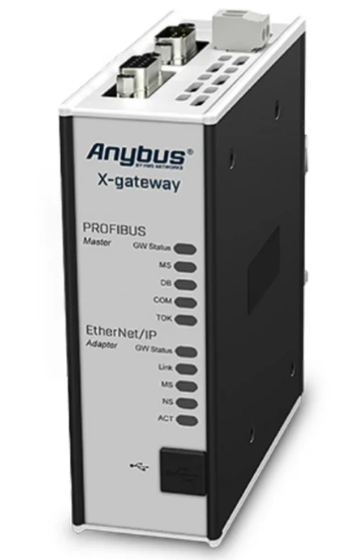 HMS Anybus AB7646-F Gateway Manual
 -
 Schneider ATV930D75N4 Inverter Manual
 -
 Mitsubishi Q2ASHCPU-S1 System Manual
 -
 Fanuc A20B-3300-0319 Board Specification
 -
 Mitsubishi QD60P8-G Counter Module Guide
 -
 Nidec Unidrive M701 Inverter Manual
 -
 ABB AO895 Analog Output Module Guide
 -
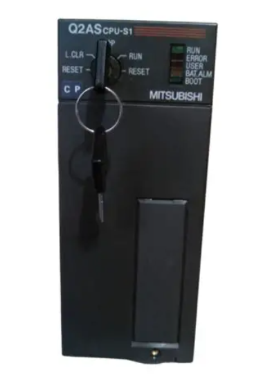 Mitsubishi Q2ASHCPU Controller System Manual
 -
 ABB Pluto S20 v2 Safety PLC Manual
 -
 Omron CJ1W-NC413 Position Module Manual
 -
 B&R X20AI4632 Analog Input Module 4 Channel
 -
 OMRON CS1G-CPU44H Ver. 4.1 CPU Unit PLC
 -
 Beckhoff EL2911-2200 TwinSAFE Logic Terminal for EtherCAT
 -
 Mitsubishi 2D-TZ368 Parallel I/O Interface Card
 -
 Mitsubishi A3ACPU PLC CPU Module for MELSEC A Series
 -
 Mitsubishi NF630-SEW 4P Adjustable Circuit Breaker 300-630A
 -
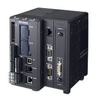 Keyence XG-8700L Multi-camera Vision System for Inspection
 -
 Beckhoff C6017-0010 Ultra Compact Industrial PC
 -
 B&R 3AT660.6 PLC Module from Automation Panel Series
 -
 GE F31X300CCHALG2 PC Board with 531X133PRUAPG1 Card
 -
 STMicroelectronics STM32L100R8T6ATR MCU Arm Cortex-M3
 -
 Omron CS1W-CLK13 Controller Link Unit
 -
 Schneider BMENOC0301 Ethernet Communication Module
 -
 HELUKABEL Braids PLC-30 40 E2UK Braided Cable Sleeve
 -
 Pe323 h0102de323a0 PLC I/O Module
 -
 Mitsubishi GT2512-STBA GT2512-STBD HMI 12.1 Inch Touch Screen
 -
 Samsung LTM213UP01 21.3 Inch LCD Monitor Panel
 -
 Allen-Bradley 440R-W23219 Guardmaster Safety Relay
 -
 Beckhoff EL2535 EtherCAT Terminal PWM Output
 -
 HELUKABEL Braids PLC-40 55 E2UK Braided Cable Sleeve
 -
 Allen Bradley 1769-OB16 16-Point Sourcing Output Module
 -
 Balluff BES 516-604-DZ-3 Delay Safety Relay for Industrial Timing
 -
 Siemens 6GK7542-1AX10-0XE0 PROFIBUS Communication Module for S7-1500
 -
 GE IC693BEM340 FIP Controller for Series 90-30 PLC
 -
 OMRON C200HG-CPU63-E Programmable Logic Controller CPU Unit
 -
 Schneider EOCR-PMZ Relay Manual
 -
 Honeywell C36TC0UA21D0 Controller Specifications
 -
 Emerson Ovation VE4001S2T2B4 Input Module
 -
 Omron CJ1M-CPU22 CPU Specifications
 -
 Grundig NEA02 AES 0 Card Specifications
 -
 Omron CJ1W-AD081-V1 Analog Input Specifications
 -
 IDEC FS1A-C21S Safety Controller Manual
 -
 IFM O3D303 Smart 3D Sensor Specifications
 -
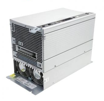
 Siemens 6SN1123-1AB00-0BA2 Power Module Guide
 -
 B&R 4PP035.0300-01 Power Panel Manual
 -
 Siemens 6ES7 153-2BA10-0XB0 IM Module
 -
 Beckhoff EL3356-0010 Analog Input Module
 -
 Siemens 3RW4037-1BB04 Soft Starter
 -
 Lenze EVF8216-E VFD
 -
 Mitsubishi GT2310-VTBA GT2310-VTBD HMI
 -
 Allen-Bradley 1764-28BXB PLC MicroLogix 1500
 -
 SP-RDM2 Relay Module Dual Reader Interface
 -
 Keyence GC-S84 Programmable Safety Controller
 -
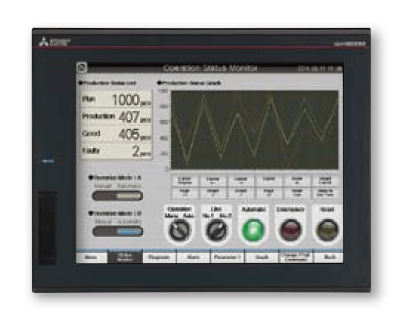 Mitsubishi GT2310-VTBA GT2310-VTBD HMI 10.4 Inch
 -
 Eurotherm MINI8 PLC Temperature Controller
 -
Mitsubishi GT2512-STBA GT2512-STBD HMI 12.1 Inch
-
 ABB ACS380-040S-02A6-4 VFD 0.75kW 480V
 -
 Dage PC514 ISSUE A PLC O.P.I Board
 -
 ROBICON 460T46.01 REV C Printed Circuit Board
 -
 Omron NX502-1300 Controller Unit NX5 CPU
 -
 B&R X20CM0985 PLC Module
 -
 Banner XS26-2DE 85064 Safety Controller
 -
 Siemens 3SK2122-1AA10 Safety Relay
 -
 HMS Anybus AB7646-F Gateway PROFIBUS EtherNet/IP
 -
 Siemens 6SN1118-0DM11-0AA0 SIMODRIVE 611 Card
 -
 Siemens C98043-A7001-L2-4 CUD1 Control Board
 -
 Stein Sohn E 083.1 PLC Rack Module 0010026-054100A
 -
 Allen Bradley 800H-2HA7P Push Button Station
 -
 Schneider BMXNRP0200 M340 PLC Module
 -
 KEPCO BOP 200-1M Bipolar Power Supply Amplifier
 -
 Mitsubishi Q2ASHCPU PLC Module with A1SX42 A1SY42 QC24-R2 A1SD75P2-S3
 -
 Siemens Siprotec 7SJ61 Overcurrent Protection
 -
 Keyence LJ-V7000 Controller Laser Profiler
 -
 Siemens 6EP3437-8SB00-0AY0 Power Supply 20A
 -
 Pasaban MC-2006 03 CAN Bus PLC Card
 -
 ETAS ES600.2 PLC Module Prototyping
 -
 ABB ACS800-01-0005-3+P901 Frequency Converter
 -
 Omron NX102-1100 PLC Module Machine Automation
 -
 Square D BMXCPS3500 PLC Power Supply Module
 -
 Allen-Bradley 96657704 Fiber Optic Converter 1771-AF
 -
 Corcom 20VK1 Power Line Filter
 -
 Novellus 2805-11407 PLC Rack Assembly
 -
 Sick RLY3-EMSS100 Safety Relay Module
 -
 Microchip PIC12F508-I/P Microcontroller
 -
 Fanuc A02B-0098-B511 Motherboard
 -
 Merlin Gerin PB80 PLC Rack Module
 -
 ABB Pluto S20 V2 CFS Safety PLC
 -
 Honeywell TK-PRR021 Redundancy Module
 -
 B&R 7XX419L.50-1 Bus Controller
 -
 Mitsubishi NV400-SW 3P 300A Breaker
 -
 B&R X20AT2222 Temperature Module
 -
 Corcom 20VK1 EMI RFI Filter
 -
 Novellus 2805-11407 PLC Rack Assy
 -
 Mitsubishi FXAOM01BD Analog Output Module 4CH
 -
 NORIS A1-91 PCB Rack Module A1-91-4 A1-91-5 A1-91-6 A1-91-7 A1-91-8
 -
 Omron ZFV-SC50 Smart Camera Vision Sensor
 -
 Schneider Electric EOCR-PMZ Motor Protection Relay
 -
 B&R X20 SO 6300 PLC Module Safety Output
 -
 Mitsubishi A2ACPU21-S1 CPU Module MELSEC
 -
 Siemens 6ES7405-0KA02-0AA0 PS405 10A Power Supply
 -
 Samsung PVU-2424 Power Supply Unit DC24V 24W
 -
 ATTO controlSYS ATT0-CPU44 PLC with Display
 -
 Lenze EPZ-10203 CANPT010W3E Absolute Encoder
 -
 GE IS215WEMAH1A+IS210BPPBH2CAA Mark VIe Embedded Processor and Backplane Power Distribution Board
 -
 GE IS215AEPAH1CH+IS210BPPBH2CAA Mark VIe Application Processor and Backplane Power Distribution Board
 -
 GE IS215WECAH1B+IS210BPPBH2CAA Mark VIe Control Platform
 -
 GE PCM Regulator for EX2100e Power Conversion Module 151X1235DB15SA1
 -
 Lenze ECSEA048C4B servo drive


