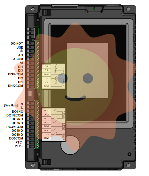
HONEYWELL 900C31-0244-00 Controller
HONEYWELL 900C31-0244-00 Controller
Product Overview
Brand: Honeywell (Honeywell)
Model: 900C31-0244-00
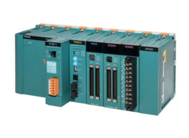
Type: controller (specific for HC900 series C30 CPU configuration)
Technical specifications and parameters
Protection grade: IP20
Ambient temperature: 1.25 ℃ (here may refer to a particular condition of the temperature, the actual operating temperature range is wider)
Control mode: pulse width modulation control mode
Communication interface: RS-485 communication interface
Current consumption: 1.56mA
Weight: 1.5KG
Colour: black and blue
Size: 23.6CM x 13.6CM x 10.6CM
Operating temperature: -1070°C (4158°F)
Storage temperature: -1085°C (-40185°F)
Relative humidity: 5%~95%, non-condensing
Functional Features
High-performance CPU: Equipped with a high-performance C30 CPU, it provides powerful data processing and control capabilities.
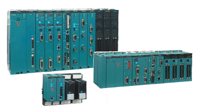
Modular design: Adopting modular design, easy to expand and maintain, and can be flexibly configured according to actual needs.
Rich communication interfaces: Support RS-485 and other communication interfaces, convenient for data exchange and communication with other devices.
Graphical Configuration Tool: Supports Windows-based Hybrid Control Designer software tool to graphically configure controllers and options, reducing the difficulty of configuration.
Easy to use: Provides friendly user interface and operation guide so that operators can get started easily.
Application Scenarios
HONEYWELL 900C31-0244-00 Controller is widely used in industrial automation control systems, such as manufacturing, energy, chemical and other fields. In these fields, the controller is able to achieve accurate data acquisition, processing and transmission, providing reliable control and monitoring functions for automation control systems.
Working Principle
Electromagnetic suction cup controller: AC voltage 380V by transformer step-down, after rectifier rectifier into 110V DC through the control device into the suction cup at this time the suction cup is magnetised, demagnetised into the reverse voltage line, the controller to achieve demagnetisation function.
Access control controller: access control controller works under two modes. One is the inspection mode, the other is the recognition mode. In the patrol mode, the controller continuously sends query codes to the card reader and receives reply commands from the card reader. This mode is maintained until the card is sensed by the reader.
When the reader senses the card, the reader generates a different reply to the controller's patrol command, in which the reader transmits the read proximity card's internal code data to the access control controller, which puts the access control controller into the recognition mode. In the recognition mode of the access control controller, the access control controller analyses the code of the proximity card, compares it with the card data stored in the device, and implements subsequent actions. After completing the action of receiving data, the access control controller will send a command to reply to the card reader, so that the card reader to restore the state, at the same time, the access control controller back to the inspection mode.
Basic Functions
Data buffer: Because the rate of I/O devices is low while the rate of CPU and memory is high, a buffer must be set in the controller. In the output, the buffer is used to store the data coming from the host at high speed, and then the data in the buffer will be transmitted to the I/O device at the rate of the I/O device; in the input, the buffer is used to store the data coming from the I/O device, and then the data in the buffer will be transmitted to the host at high speed after a batch of data has been received.
Error control: The device controller also manages error detection of data sent from I/O devices. If an error is found in the transmission, the error detection code is usually set and reported to the CPU, which then cancels the transmitted data and transmits it again. This ensures the correctness of the data input.
Data exchange: This refers to the realisation of data exchange between the CPU and the controller, and between the controller and the device. For the former, it is through the data bus, by the CPU in parallel to write data into the controller, or from the controller in parallel to read out the data; for the latter, it is the device will be the data input to the controller, or from the controller to the device. For this purpose, data registers shall be set up in the controller.
Status Description: Identifies and reports the status of the device The controller shall note down the status of the device for the CPU to know. For example, the CPU can start the controller to read data from the device only when the device is in a transmit-ready state. For this purpose, a status register shall be set up in the controller with each bit therein reflecting a particular state of the device. When the CPU reads in the contents of this register, it will know the state of the device.
Receive and recognise commands: The CPU can send many different commands to the controller, and the device controller should be able to receive and recognise these commands. To this end, there should be a corresponding control register in the controller to store the received commands and parameters, and decode the received commands. For example, the disk controller can receive Read, Write, Format and other 15 different commands from the CPU, and some commands also have parameters; accordingly, there are several registers and command decoders in the disk controller.
Address recognition: Just as each unit in memory has an address, so does each device in the system, and the device controller must be able to recognise the address of each device it controls. In addition, in order for the CPU to be able to write to (or read from) registers, these registers should all have unique addresses.

- User name Member Level Quantity Specification Purchase Date
- Satisfaction :
-


