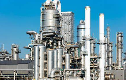
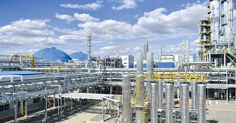
Control scheme of typical chemical unit
▲ Pressure control system
1) Gas pressure
Gas pressure is similar to liquid level in that it is a measure of the imbalance in and out of the material in the system, so the pressure control of the gas changes either the inflow or the outflow.
2) Liquid pressure
Because of the incompressibility of the liquid, the pressure control of the liquid is very similar to the flow control
3) Steam pressure
Common boiler drum pressure control, rectification tower, evaporator pressure control, which is essentially the control of heat transfer, the steam pressure of the system characterizes the state of heat balance. So in this kind of control system its characteristics are in some ways similar to temperature control.
(4) Liquid level control system
The liquid level of a equipment or storage tank represents the accumulation of the difference between its inflow and outflow. In chemical production, due to the continuity of production, liquid level control is to serve the material balance, and liquid level control should be completed.

Keep the retention in the equipment or storage tank within the specified high and low limits, so that they have a certain buffer capacity;
At each retention rate, the balance between the inlet flow and the outlet flow is maintained most of the time;
Through the buffer volume to maintain the balance of the load before and after the process, when the flow needs to change, it is hoped that the flow can be gradually and smoothly adjusted.
(5) Component control system
In the production site, the most problematic is often the component control system. The object of the component control system is also multi-capacity, and the time constant is large, and the pure lag time is large. The reasons for the poor work of the component control system, as well as the structure of the analyzer itself is relatively complex, the sampling system and the sample pretreatment part are not working well, and the pure lag is too large. In general, when a suitable component analyzer is not selected, indirect controlled variables such as temperature and temperature difference can also be used instead.
1.Requirements for selecting control instruments
Accurate and reliable, high sensitivity, rapid response, small lag, easy to use and maintain, cheap price.
2.Control scheme of typical chemical unit
▲ Reactor
Requirements for reaction control:
1) Make the reaction reach the specified conversion rate or the product reach the specified concentration.
2) The processing capacity is relatively stable. For example, in a reaction system with material circulation, in order to maintain material balance, necessary auxiliary adjustment systems should be configured, such as automatic empouting or elimination of inert materials.
3) In order to prevent the process parameters from entering the dangerous area or abnormal working conditions, some alarm, interlock or automatic selective adjustment system should be configured to send a signal when the process parameters are outside the normal range, and some valves should be opened, cut off or kept in the restricted position when approaching the dangerous area.

Reaction control scheme:
▲ rectification
Distillation is a common liquid-liquid separation method, and the main purpose of distillation control is to meet the specified separation requirements. The main variables are feed amount, composition, temperature, operating pressure, cooling and heating medium, pressure and temperature transformation.
3.Energy Consumption Calculation
At present, the common task facing mankind is to protect resources, reduce environmental pollution, maintain ecological balance and achieve sustainable development. The heat transfer process in chemical production is a frequent occurrence, so the rational use of energy and saving energy consumption are the responsibilities of each chemical process designer. The common methods of process energy analysis are: pinch point analysis and three-link energy analysis. Common energy saving measures are as follows:
Select the appropriate reaction pressure or temperature.
Improve the reaction conversion rate and reduce the occurrence of side reactions: Choose advanced reactors or reaction processes, and can also use catalysts with strong selectivity and high conversion rate.
Select advanced process routes and raw material routes.
Select the appropriate equipment, optimize the operating conditions, and reduce the energy consumption of the separation process.
The selection of efficient equipment and new insulation materials, such as the selection of efficient pumps.
Pay attention to waste heat recovery and energy recovery.
In the whole process, the step-by-step use of heat energy should be considered, and cold and fever should be avoided.

4.Security Settings
In the PID design phase, you must work with the automation professional to design the necessary safety protection facilities. The safety control of hazardous materials in chemical equipment and storage and transportation is one of the most effective measures for fire and explosion prevention.
4.1 Layout of the plant area and each chemical plant area
Fire protection design, fire alarm system should be implemented in accordance with the "Design Code for Fire Protection of Petrochemical Enterprises" (GB50160-92), as revised in 1999;
The classification of explosion danger zones for chemical production plants and tank farms shall be carried out in accordance with the "Code for Design of Electric Devices in Explosion and Fire Dangerous Environment" (GB50058-92).
The anti-lightning and anti-static systems in chemical plant, tank farm and oil loading and unloading area shall be implemented in accordance with the Design Code for Lightning Protection of Building Materials (GB50057-92)2000 edition;
The fire protection design of various buildings in the plant shall be implemented in accordance with the Code for Fire Protection in Building Design (GBJ16-87), 2001;
The treatment process design of toxic materials should be implemented in accordance with the "Health Standard for Industrial Enterprise Design" (GBZ1-2002).
If the user has requirements, as long as it does not violate the above main standards, it can also be according to the user's requirements. In order to secure and reliable design, the engineering design should refer to the applicable standard specifications according to the specific conditions of the contract and the project, and when the basis is not found in the standard specifications, the corresponding design manual and empirical data are supplemented.

4.2 Common Security Risks
▲ Equipment and pumps and other exits are blocked
The outlet of almost all containers, pumps, compressors, flame heaters or other equipment can be blocked due to mechanical failure or human accident. In this case, the bleed load usually refers to the maximum flow rate produced by the pump, compressor, or other flow source under pressure relief conditions.
▲ Fire
Fire is one of the most difficult accidents to predict in a chemical plant, but this situation can be a condition that produces the greatest drainage requirements. If a plant-wide fire is possible, then the size of the entire drainage system can be determined on this condition. However, because the equipment can be distributed in zones, the impact of fire on the safety system is limited to a certain area. In the area of germanium tank with a large number of uninsulated germanium tanks, more steam will be generated. The various empirical formulas described above can be used to determine the discharge rate of a vessel exposed to a flame, depending on the system and fluid under consideration. A fire may overpressure a vapor-filled, liquid-filled, or mixed phase system.
▲ Pipeline rupture
When there is a large difference between the design pressure on the inside of the shell of the heat exchanger and the design pressure on the side of the tube (usually the ratio is 1.5 to 1 or greater), pressure relief measures should be taken on the low pressure side. Usually only one pipe break is considered in the design. The leakage volume of a broken pipe can be calculated by proper formula. When the cold medium is in contact with the heat flow, the effect of rapid evaporation should be taken into account, as should the possibility of instantaneous overpressure caused by the sudden release of vapor into the all-liquid phase system.
▲ Control valve failure
The possible failure of the instrument and control valve should be carefully estimated. In fact, the failure of the control valve may not be in the expected position. Valves can get stuck or there is a problem with the control loop, so safety protection should also be provided for these factors. In this case, the size design of the safety valve should be based on the flow coefficient (manufacturer's data) and pressure difference of the specific control valve and the device involved.

▲ Thermal expansion
If the process line is isolated on the cold side of the heat exchanger, the pressure relief valve protection should be installed on the line or on the cold side of the heat exchanger because the heat input from the hot side will cause overpressure.
If equipment or lines are isolated when filled with liquid, a safety valve should be installed to prevent expansion of the liquid in them. Solar radiation or atmospheric temperature changes require thermal expansion protection, and flash through the safety valve also needs to be considered.
▲ Utility failures
Sometimes regional or plant-wide cooling water leaks can occur, affecting fractionators and other water-cooling equipment. When determining the size of the flare system, the cooling water failure is usually the decisive condition.
As with cooling water system failures, power failures can occur in one area or plant wide, resulting in multiple effects. Since electric pumps and motor driven air coolers are often used in each process device, a power supply accident will immediately cause the simultaneous shutdown of electrical equipment. Power supply failure will be the main factor affecting the bleed capacity.
Failure of the instrument air system, whether or not related to a power failure, should be considered in determining the size of the system, because the pneumatic control circuit will be interrupted by failure.
- ABB
- General Electric
- EMERSON
- Honeywell
- HIMA
- ALSTOM
- Rolls-Royce
- MOTOROLA
- Rockwell
- Siemens
- Woodward
- YOKOGAWA
- FOXBORO
- KOLLMORGEN
- MOOG
- KB
- YAMAHA
- BENDER
- TEKTRONIX
- Westinghouse
- AMAT
- AB
- XYCOM
- Yaskawa
- B&R
- Schneider
- Kongsberg
- NI
- WATLOW
- ProSoft
- SEW
- ADVANCED
- Reliance
- TRICONEX
- METSO
- MAN
- Advantest
- STUDER
- KONGSBERG
- DANAHER MOTION
- Bently
- Galil
- EATON
- MOLEX
- DEIF
- B&W
- ZYGO
- Aerotech
- DANFOSS
- Beijer
- Moxa
- Rexroth
- Johnson
- WAGO
- TOSHIBA
- BMCM
- SMC
- HITACHI
- HIRSCHMANN
- Application field
- XP POWER
- CTI
- TRICON
- STOBER
- Thinklogical
- Horner Automation
- Meggitt
- Fanuc
- Baldor
- SHINKAWA
- Other Brands


