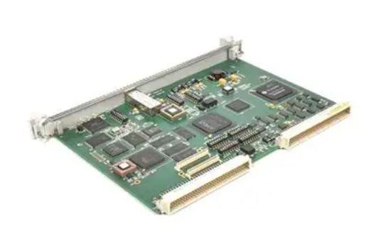
GE VMIVME-565-010000 (part number: 332-01565-010000P) is a high-performance reflective memory module based on the VME bus architecture, belonging to the GE Industrial Real time Control and Data Communication product series. This module is designed specifically for the high-speed data sharing requirements of multi node devices in industrial control systems. It uses "reflective memory" technology to build a real-time data exchange network, allowing multiple controllers or processors to access shared memory space with extremely low latency, achieving synchronous updates and efficient interaction of data, and providing core data communication support for high real-time industrial scenarios.
GE VMIVME-5565-010000 332-01565-010000P Reflective Memory
Product Overview
GE VMIVME-565-010000 (part number: 332-01565-010000P) is a high-performance reflective memory module based on the VME bus architecture, belonging to the GE Industrial Real time Control and Data Communication product series. This module is designed specifically for the high-speed data sharing requirements of multi node devices in industrial control systems. It uses "reflective memory" technology to build a real-time data exchange network, allowing multiple controllers or processors to access shared memory space with extremely low latency, achieving synchronous updates and efficient interaction of data, and providing core data communication support for high real-time industrial scenarios.
As an industrial grade real-time communication component, this module, with microsecond level data transmission delay, high reliability, and flexible network topology capabilities, is widely compatible with GE VME series controllers and third-party VME bus devices. It plays a key role in fields such as aerospace, rail transit, and industrial control that require strict real-time and stability data interaction, and is the core equipment for building distributed real-time control systems.
Core technical characteristics
1. High speed reflective memory technology to achieve microsecond level data sharing
The module adopts a dedicated reflective memory control chip and constructs a real-time data exchange mechanism based on memory mapping. The shared memory capacity can reach 16MB and supports 32-bit/64 bit data read and write operations. The data transmission delay is as low as 1.5 microseconds, far superior to traditional Ethernet communication. Multiple node devices can directly access shared memory through modules, without the need for complex protocol parsing and data packaging processes, ensuring "zero latency" synchronous updates of data in distributed systems. Simultaneously supporting data broadcasting mode, single node data updates can be synchronized in real-time to all nodes in the network, meeting the requirements of multi device collaborative control.
2. Flexible network topology, adaptable to multi scenario deployment
The module supports various network topologies such as star, ring, and bus. A single reflective memory network can connect up to 32 node devices, and can be connected between nodes through fiber optic or twisted pair interfaces. The fiber optic transmission distance can reach up to 10 kilometers, and the twisted pair transmission distance supports 100 meters, meeting the wiring needs of different industrial sites. Supporting hot swapping function, the access or removal of node devices will not affect the normal operation of the entire reflective memory network, greatly enhancing the flexibility of system deployment and expansion.
3. Industrial grade reliability and fault-tolerant design
The module adopts the VME64x bus standard design, with complete electrical isolation and electromagnetic shielding performance. The anti-interference level meets the IEC 61000-4-2/3/4/6 standard, and can resist static electricity, pulse trains, surges, and radio frequency interference in industrial sites. Built in data verification and error detection mechanism, supports CRC-32 data verification, can automatically identify and correct errors in data transmission process, and has node fault detection function. When a node has communication abnormalities, it can quickly isolate the faulty node to avoid affecting the entire network data transmission. The mean time between failures (MTBF) exceeds 300000 hours, ensuring stable operation in extreme industrial environments.
4. Seamless compatibility with VME bus system, easy deployment
The module is fully compatible with the VME64x bus specification and can be directly plugged into standard VME racks, enabling plug and play with GE VMIVME series controllers, processors, and third-party VME bus devices without the need for additional hardware adaptation. Support parameter configuration through GE dedicated configuration software or VME bus interface, allowing flexible setting of shared memory partitions, node IDs, communication rates, and other parameters. At the same time, provide a comprehensive API development package that supports multiple programming languages such as C, C++, LabVIEW, etc., making it easy for users to quickly integrate into existing control systems.
5. Comprehensive diagnostic and monitoring functions
The module integrates real-time status monitoring and fault diagnosis functions, visually displaying power status, network connection status, data transmission status, and fault alarm information through LED indicator lights. It also supports uploading device status, network performance, fault logs, and other information to the controller or monitoring system through the VME bus. Provide network load monitoring function, which can real-time calculate performance indicators such as data transmission rate and packet loss rate, helping maintenance personnel predict network bottlenecks in advance and ensure stable system operation.
Key technical parameters
Product Model
VMIVME-5565-010000 (Material Number: 332-01565-010000P)
Bus standard
VME64x, Compatible with VMEbus Rev. C. specification
Shared memory capacity
16MB (expandable to 64MB)
Data transmission delay
Typical value is 1.5 microseconds, maximum value is 2 microseconds
communication interface
2 fiber optic interfaces (ST/SC optional), 1 twisted pair interface (RJ45)
transmission rate
Fiber optic: up to 1Gbps; Twisted pair cable: 100Mbps
Number of supported nodes
Up to 32 nodes per network
transmission distance
Fiber optic: multimode 500 meters, single-mode 10 kilometers; Twisted pair cable: 100 meters
data validation
CRC-32 cyclic redundancy check
power supply
Provided by VME rack with+5V DC,+12V DC, -12V DC
power consumption
Typical value of 12W, maximum value of 15W
working environment
Temperature: -40 ℃~75 ℃; Humidity: 5%~95% (no condensation)
Protection level
IP20 (front panel)
MTBF
≥ 300000 hours
Dimensions (length x width x height)
160mm × 100mm × 233mm (standard 3U VME module size)
Installation and maintenance precautions
1. Installation specifications
-The module needs to be installed on a 3U standard rack that complies with the VME64x specification. Before installation, it is necessary to confirm that the rack power supply voltage is stable and that all power supply pins are in good contact to avoid module damage caused by abnormal power supply;
-When inserting the module, it should be smoothly pushed along the rack guide rail to ensure that the module is fully engaged with the VME backplane interface, and the screws are tightened in place to prevent poor contact caused by vibration;
-When connecting optical fibers, it is necessary to clean the fiber optic joints to avoid signal attenuation caused by dust pollution. The bending radius of the optical fiber should not be less than 30mm to prevent fiber breakage;
-When connecting twisted pair cables, Category 5e or higher shielded twisted pair cables should be used, with the shielding layer grounded at one end and laid parallel to the strong current cable for a minimum distance of 50cm to avoid electromagnetic interference;
-After the network topology is built, it is necessary to set the node IDs (ensuring uniqueness), shared memory partitions, and communication parameters through configuration software to verify that data transmission between nodes is normal, without packet loss or delay abnormalities.
2. Daily maintenance
-It is recommended to conduct a comprehensive inspection of the module every 6 months, clean the dust on the front panel, interfaces, and heat dissipation holes, check whether the fiber/twisted pair connectors are loose or oxidized, and clean or replace them if necessary;
-Monitor network transmission performance every month through monitoring systems or configuration software, including latency, packet loss rate, load rate, and other indicators, to ensure compliance with system design requirements. If any abnormalities occur, promptly troubleshoot line or node faults;
-Regularly backup module configuration parameters, including node ID, memory partition, communication rate, etc., to avoid configuration loss caused by module failures;
-When a module malfunctions, the rack power should be turned off before replacement. Before replacement, the original module configuration parameters should be recorded. After installing the new module, the configuration needs to be re imported and network connectivity testing should be conducted;
-Modules that have been idle for a long time should be stored in a dry, ventilated, and non corrosive gas environment, with a storage temperature range of -55 ℃~85 ℃. The network communication performance should be tested every 12 months by powering on.
Application scenarios
This module, with its high-speed, real-time, and highly reliable data sharing capabilities, is widely used in industrial scenarios that require strict real-time performance
1. Aerospace: Data synchronization among multiple simulation computers in the aircraft simulation testing system, real-time interaction of flight control data, ensuring simulation accuracy and real-time performance;
2. Rail Transit: In high-speed rail/subway signal control systems, real-time sharing of train position and speed data between multiple regional controllers supports train interval control and scheduling;
3. Industrial control: In the distributed control system (DCS) of large metallurgical and chemical enterprises, process parameters and equipment status data are synchronized among multiple controllers to achieve collaborative control;
4. Energy and electricity: In the control system of power plant generator sets, real-time data exchange between excitation controllers, speed controllers, and protection devices ensures stable operation of the units;
5. National Defense and Military Industry: In the weapon and equipment testing system, high-speed data transmission between multi node data acquisition equipment and the main control system supports real-time testing and data analysis;
6. Medical equipment: In high-end medical imaging equipment, high-speed data sharing between image acquisition modules and processing modules improves image processing efficiency and accuracy.
- User name Member Level Quantity Specification Purchase Date
- Satisfaction :
-


