ControlLogix AutoMax DCSNet and AutoMax Remote I/O Communication Interface Module
Remote I/O Communication Interface Module
Important User Information
Because of the variety of uses for the products described in this publication, those responsible for the application and use of this control equipment must satisfy,themselves that all necessary steps have been taken to assure that each application and use meets all performance and safety requirements, including any applicable laws, regulations, codes and standards.
The illustrations, charts, sample programs and layout examples shown in this guide are intended solely for purposes of example. Since there are many variables and requirements associated with any particular installation, Rockwell Automation does not assume responsibility or liability (to include intellectual property liability) for actual use based upon the examples shown in this publication.
Allen-Bradley publication SGI-1.1, Safety Guidelines for the Application, Installation and Maintenance of Solid-State Control (available from your local Rockwell Automation office), describes some important differences between solid-state equipment and
electromechanical devices that should be taken into consideration when applying products such as those described in this publication. Reproduction of the contents of this copyrighted publication, in whole or part, without written permission of Rockwell Automation, is prohibited.

Understand Compliance to European Union Directive
If this product bears the CE marking, it is approved for installation within the European Union and EEA regions. It has been designed and tested to meet the following directives.
EMC Directive
This product is tested to meet Council Directive 89/336/EEC Electromagnetic .Compatibility (EMC) and the following standards, in whole or in part, documented in a technical construction file:
• EN 50081-2 EMC - Generic Emission Standard, Part 2 - Industrial Environment
• EN 50082-2 EMC - Generic Immunity Standard, Part 2 - Industrial Environment
This product is intended for use in an industrial environment.
Low Voltage Directive
This product is tested to meet Council Directive 73/23/EEC Low Voltage, by applying the safety requirements of EN 61131-2 Programmable Controllers, Part 2 -Equipment Requirements and Tests.For specific information required by EN 61131-2, see the appropriate sections in this publication, as well as the following Allen-Bradley publications:
• Industrial Automation Wiring and Grounding Guidelines, publication 1770-4.1
• Automation Systems Catalog, publication B113
Open style devices must be provided with environmental and safety protection by proper mounting in enclosures designed for specific application conditions. See NEMA Standards publication 250 and IEC publication 529, as applicable, for explanations of the degrees of protection provided by different types of enclosure.
Set the Network Type and Node Address Switches
Before you install the module, you must set the network type, drop number and drop depth using the switches at the top of the module.The two switches at the left set the drop depth, the two at the right set the drop number.
The following table shows how to set the switches for each mode of operation.

For example, to configure the 56AMXN/B as a DCS slave with drop number 17,drop depth 5, set the switches to 0, 5, 1, and 7 from left to right.Any other settings are invalid and result in the module going into “Thumbwheel test” mode. In thumbwheel test mode, the display shows the current switch settings.It doesn’t go out of thumbwheel test mode until you cycle power.In thumbwheel test mode, the 56AMXN/B initially displays “Thumb Test Mode” on the 4-character display, displays the switch settings for 5 seconds, then resumes displaying “Thumb Test Mode” For DCS slave operation, if the drop number and drop depth are individually valid,but the combination results in invalid drop numbers (for example, drop number 55,drop depth 2), the module displays an error message on the 4-character display but does not enter Thumbwheel test mode.
Prepare the Chassis for Module Installation
Before you install the 56AMXN/B module, you must install and connect a ControlLogix chassis and power supply.

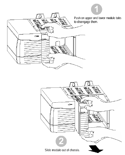
Installing or Removing the Module While Power Is Applied
Versions of the 56AMXN hardware prior to O-57677-1 do NOT support removal and insertion under power.
The hardware version can be identified by looking for a sticker with the part number O-57677-1 or above on the module’s printed circuit (near the serial number – you do not need to disassemble the 56AMXN to find the sticker). Modules with no stickers are hardware version O-57677 and do NOT support removal and insertion under power ,For hardware versions O-57677-1 and above, you can install or remove the module ,while chassis power is applied if you observe the following precautions.
When you insert or remove a module while backplane
power is on, an electrical arc may occur. 
• sending an erroneous signal to your system’s actuators
causing unintended machine motion or loss of process
control.
• causing an explosion in a hazardous environment.Repeated electrical arcing causes excessive wear to contacts on both the module and its mating connector. Worn contacts may create electrical resistance that can affect module operation.

Wire the Connector for the AutoMax Network
Use a drop cable, 612574-36R, available through Rockwell Automation Systems Business, and passive tap M/N 57C380 to connect the module to the coaxial network cable. This cable turns down and has a ferrite to reduce EMI. This cable must be used in CE applications. You can also use drop cable 612403-036R but it points up.
The drop cable is a 3-foot long multi-conductor cable with 9-pin D-shell connectors at each end. Connect one end to the connector on the module and the other end to the passive tap.
The passive tap has two BNC connectors for connection to the coaxial cables and terminating loads.
The network coaxial cable must be terminated with 75 ohm terminating loads attached to the taps at the physical ends of the network. There should be two and only two terminators on the network.
For DCS, the network cable can be RG-59/U or RG-11/U. For remote I/O, the cable must be RG-59/U.
Check Power Supply and Module Status
The rack power supply indicator should be green.
The module OK LED should be solid red, then solid green.
The alphanumeric display shows the following messages at powerup.
OK LED – Module Health
A bicolor OK LED indicates module health. A red LED indicates that module startup diagnostics have failed or a major module fault such as watchdog bite or jabber inhibit has occurred. Green indicates that the card has passed all power-up diagnostics and is functioning normally. This LED is red during powerup.
If all three LEDs are solid red and the 4-character display shows something like M#66, this indicates that a fatal error has occurred. Refer to the User Guide for information on clearing fatal errors.
Where to Find Information on Configuring Your 56AMXN/B Module
Now that you have installed your AutoMax DCS/RIO module, you must configure it. For this information, refer to the configuration chapters of your 56AMXN User’s Guide, publication 56AMXN-UM002A-EN-P.
This manual is supplied on the 56AMXN/B distribution CD. The CD also contains the Adobe PDF reader.
Hazardous Location information
The following information applies when operating this equipment in hazardous locations:
The 56AMXN is NOT suitable for use in hazardous locations.Products marked “CL I, DIV 2, GP A, B, C, D” are suitable for use in Class I Division 2 Groups A, B, C, D, Hazardous Locations and nonhazardous locations only. Each product is supplied with markings on the rating nameplate indicating the hazardous location temperature code. When combining products within a system,the most adverse temperature code (lowest “T” number) may be used to help determine the overall temperature code of the system. Combinations of equipment in your system are subject to investigation by the local Authority Having Jurisdiction
at the time of installation

- ABB
- General Electric
- EMERSON
- Honeywell
- HIMA
- ALSTOM
- Rolls-Royce
- MOTOROLA
- Rockwell
- Siemens
- Woodward
- YOKOGAWA
- FOXBORO
- KOLLMORGEN
- MOOG
- KB
- YAMAHA
- BENDER
- TEKTRONIX
- Westinghouse
- AMAT
- AB
- XYCOM
- Yaskawa
- B&R
- Schneider
- Kongsberg
- NI
- WATLOW
- ProSoft
- SEW
- ADVANCED
- Reliance
- TRICONEX
- METSO
- MAN
- Advantest
- STUDER
- KONGSBERG
- DANAHER MOTION
- Bently
- Galil
- EATON
- MOLEX
- DEIF
- B&W
- ZYGO
- Aerotech
- DANFOSS
- Beijer
- Moxa
- Rexroth
- Johnson
- WAGO
- TOSHIBA
- BMCM
- SMC
- HITACHI
- HIRSCHMANN
- Application field
- XP POWER
- CTI
- TRICON
- STOBER
- Thinklogical
- Horner Automation
- Meggitt
- Fanuc
- Baldor
- SHINKAWA
- Other Brands


