The core positioning of the XVC768AE102 3BHB007211R0102 analog input module is an "industrial grade high-precision signal acquisition unit". Its design revolves around the three core requirements of "ultra-high precision, super strong anti-interference, and high reliability".
ABB XVC768AE102 3BHB007211R0102 Analog Input Module
Core positioning and technical characteristics
The core positioning of the XVC768AE102 3BHB007211R0102 analog input module is an "industrial grade high-precision signal acquisition unit". Its design revolves around the three core requirements of "ultra-high precision, super strong anti-interference, and high reliability". Compared with conventional analog input modules, it has the following outstanding technical characteristics:
1. Ultra high precision signal acquisition: using a 24 bit high-resolution Δ ∑ type AD conversion chip, combined with a high-precision signal conditioning circuit, the acquisition accuracy reaches ± 0.01% FS, and the temperature drift is controlled within ± 10ppm/℃, far superior to the industry's conventional standards; Supports 16 differential analog input channels, with mutual isolation between channels, capable of simultaneously collecting multiple types of high-precision signals, meeting the multi parameter monitoring needs of complex industrial scenarios.
2. Multi type signal compatibility: with strong signal adaptation capability, a single module can be flexibly configured as thermocouple (TC) mode (supporting K, E, J, T, S and other full series types), thermal resistance (RTD) mode (supporting PT100, PT1000, Cu50, etc.) and standard electrical signal mode (4-20mA, 0-10V, 0-5V), and can adapt to different sensor types without replacing the module to improve the flexibility of system configuration.
3. Multiple anti-interference and protection: Adopting a three-level isolation design of "channel module system", the isolation voltage between channels reaches 2500Vrms, and the isolation voltage between modules and systems reaches 1500Vrms; Built in multi-level EMC filtering circuit, compliant with IEC 61000-4 series electromagnetic compatibility standards, can effectively resist common mode interference, series mode interference, and surge impact in industrial sites; Simultaneously equipped with overcurrent, overvoltage, and disconnection detection protection functions, ensuring the safety of modules and sensors.
4. High speed data transmission capability: Supports high-speed industrial buses such as PROFIBUS DP-V2 and EtherNet/IP, with communication speeds up to 100Mbps and bus cycle times as short as 0.1ms. It can upload high-precision data collected in real time to the controller, meeting the high real-time requirements of industrial control.
5. Extreme environmental adaptability: using wide temperature industrial grade components, the working temperature range covers -40 ℃~+70 ℃, and the storage temperature range is -55 ℃~+85 ℃; Equipped with IP20 protection level, it can withstand dust, vibration (in accordance with IEC 60068-2-6 standard) and wide range power input (DC 24V ± 20%) in industrial sites, with an average time between failures (MTBF) of over 300000 hours.
Core functions and application value
The XVC768AE102 3BHB007211R0102 analog input module, as the "data acquisition front-end core" of industrial control systems, focuses on precise acquisition, intelligent processing, and reliable transmission of analog signals. The specific core functions and application value are as follows:
1. Precise acquisition and conditioning of multiple types of signals
The module is equipped with dedicated conditioning circuits for different types of signals: for thermocouple signals, it integrates high-precision cold end compensation circuits (compensation accuracy ± 0.1 ℃), effectively eliminating the influence of environmental temperature on measurement results, supporting wire breakage detection and fault alarm; For thermal resistance signals, a 4-wire/3-wire wiring mode is adopted to reduce measurement errors caused by wire resistance and ensure temperature measurement accuracy; For standard electrical signals such as 4-20mA, distortion free acquisition is achieved through high-precision sampling resistors and low-noise operational amplifiers. The built-in digital filtering algorithm can adjust the filtering level according to requirements to filter out high-frequency noise interference. In the boiler control system of thermal power units, key parameters such as furnace temperature (S-type thermocouple), main steam temperature (PT100), and feedwater pressure (4-20mA) can be collected simultaneously, providing accurate data basis for boiler combustion control.
2. Intelligent fault diagnosis and warning
Integrated with comprehensive intelligent diagnostic functions, it can monitor the module's own status (power supply, bus communication, AD conversion unit) and channel status (signal over range, disconnection, short circuit, sensor failure) in real time. When abnormalities are detected, detailed fault information (including fault channel address, fault type, fault occurrence time) is immediately uploaded to the upper system through the bus. At the same time, graded alarms are generated through the module's own LED indicator lights (power light PWR, running light RUN, fault light ERR, channel status light CHx). In the conventional island control system of nuclear power, this function can quickly locate the fault point, provide accurate fault information for operation and maintenance personnel, shorten the troubleshooting time, and improve system safety redundancy.
3. Flexible parameter configuration and calibration
Support parameter configuration through specialized software such as ABB Control Builder M and Symphony Plus Engineering. Signal type, sampling rate (adjustable from 10Hz-1000Hz), alarm threshold, filtering level, and other parameters can be independently set for each channel to meet the measurement needs of different process scenarios; The module supports two modes: automatic calibration and manual calibration. Channel accuracy calibration can be completed through software without disassembling the module, simplifying the calibration process and reducing operation and maintenance costs. In the control system of chemical reaction vessels, the sampling rate and alarm threshold of temperature and pressure channels can be flexibly adjusted according to the needs of different reaction stages to improve control accuracy.
4. Redundant design and high reliability assurance
Support module level and bus level dual redundancy configuration, which can be used in conjunction with redundant controllers and buses. When the main module or bus fails, the system can complete redundancy switching in milliseconds to ensure uninterrupted data acquisition; The module power unit adopts redundant design, supports dual power input, and further enhances the reliability of system operation. In large-scale hydrogenation units in the petrochemical industry, redundant design can effectively avoid production interruptions caused by module failures and ensure the continuous and stable operation of the unit.
5. Convenient maintenance and hot swappable function
Supports hot swapping function, allowing for module installation, replacement, and maintenance without shutting down the system. With modular wiring terminals and clear labeling, it greatly simplifies the on-site wiring and maintenance process; The module has a built-in storage unit that can locally save configuration parameters and fault logs. After replacing the module, there is no need to reconfigure the parameters, and it can be directly imported to resume operation. In the control system of the continuous casting machine in the metallurgical plant, the hot plug function can replace faulty modules without interrupting the continuous casting process, avoiding significant economic losses caused by unplanned shutdowns.
Structural composition and key interfaces
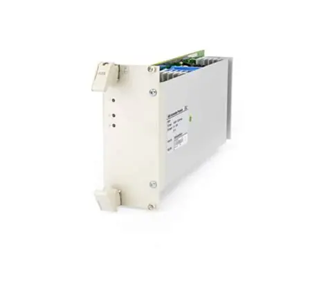
The XVC768AE102 3BHB007211R0102 analog input module adopts a standardized industrial packaging design, with a compact structure and easy installation and maintenance. It mainly consists of a signal acquisition and conditioning unit, an AD conversion unit, a core control unit, a bus communication unit, a power supply unit, and a status indication unit. The functions of each part complement each other
component
core component
Key interfaces/features
function and role
Signal acquisition and conditioning unit
High precision operational amplifier, cold junction compensation chip, isolation chip
16 differential input channels, supporting TC/RTD/4-20mA/0-10V
Realize the acquisition, conditioning, isolation and conversion of various analog signals
AD conversion unit
24 bit Δ ∑ type AD conversion chip, clock chip
Conversion accuracy ± 0.01% FS, sampling rate adjustable from 10Hz-1000Hz
Convert analog signals into high-precision digital signals
Core control unit
32-bit high-performance microprocessor, program memory, data memory
Support multi-channel parallel processing and built-in fault diagnosis algorithm
Coordinate signal processing, parameter calculation, fault diagnosis, and instruction distribution
Bus communication unit
High speed bus controller, optoelectronic isolation chip
1 PROFIBUS DP-V2/1 EtherNet/IP, with a maximum speed of 100Mbps
Realize high-speed data exchange with the controller and upper system
Power supply unit
Wide range redundant power module, overcurrent and overvoltage protection circuit
Input: DC 24V ± 20%, supports dual power redundant input
Provide stable and secure redundant power supply for each unit of the module
Status indicator unit
LED indicator light group
PWR (power supply), RUN (running), ERR (fault), CHx (channel status)
Intuitive feedback module and operational status of each channel for easy troubleshooting
Key points for installation, debugging, usage, and maintenance
To fully leverage the performance advantages of the XVC768AE102 3BHB007211R0102 analog input module and ensure long-term stable operation of the control system, it is necessary to strictly follow the following installation, commissioning, and maintenance specifications:
1. Installation specifications
-The module needs to be installed on standard DIN rails and is recommended to be installed in a 19 inch enclosed control cabinet. The installation position should be away from high-temperature heat sources (such as power modules, heaters) and strong electromagnetic radiation sources (such as frequency converters, traction inverters), ensuring good ventilation or equipped with cooling fans in the control cabinet. The ambient temperature should be controlled at -40 ℃~+70 ℃, and the humidity should be 5%~95% without condensation.
-When wiring, it is necessary to strictly distinguish between power terminals, signal input terminals, and bus communication terminals: the power line uses 2.5mm ² copper core cables, which are separately wired and equipped with 1A fuses; The thermocouple signal uses a dedicated compensation wire, the thermal resistance signal is preferentially wired using a 4-wire system, and the analog signal uses shielded twisted pair (shielded layer single ended grounding, grounding resistance less than 1 Ω); The bus line adopts a dedicated industrial bus cable, and the bus end module needs to be connected to a matching terminal resistor.
-The module installation should be firm to avoid loose wiring caused by equipment vibration; When multiple modules are installed side by side, the spacing between modules should not be less than 10mm to ensure good heat dissipation; After the wiring is completed, a torque wrench should be used to tighten the terminals to the specified torque (1.2N · m) to avoid false connections that may cause signal abnormalities.
2. Key debugging points
-Before debugging, module parameter configuration needs to be completed through dedicated software, including bus address, communication rate, signal types of each channel, sampling rate, alarm threshold, filtering level, etc., to ensure consistency with the communication protocol and parameters of the controller; For thermocouple channels, it is necessary to set the cold end compensation method (internal compensation/external compensation) in the software.
-When power on debugging, first connect the redundant power supply of the module, observe whether the PWR light is always on (when the dual power supply is normal, the dual lights are on), then connect the power supply of the controller, check the status of the RUN light (always on) and communication light (flashing), and confirm that the communication between the module and the controller is normal; Subsequently, precision calibration is performed on each channel, and standard signals at 0% FS, 50% FS, and 100% FS points are input through a standard signal generator to verify whether the acquisition accuracy meets the requirements.
-During the system integration phase, simulate various working conditions on site (such as signal over range, sensor disconnection), and test whether the module fault diagnosis function is normal; Simultaneously test the redundancy switching function, manually disconnect the main module or power supply, and observe whether the system can quickly complete the redundancy switching to ensure uninterrupted data acquisition.
3. Daily maintenance
-During daily inspections, focus on observing the status of module indicator lights, checking the temperature and humidity inside the control cabinet, cleaning the surface dust of the module (using a dry soft cloth), and ensuring that the module has no abnormal heating phenomenon (surface temperature does not exceed 60 ℃).
-Regularly check the module operation logs through the upper system every month, analyze the fluctuation of channel signals, focus on abnormal records such as signal over range, communication interruption, sensor failure, etc., and promptly investigate potential problems; Sample calibration of key channels to verify collection accuracy.
-Conduct a comprehensive inspection of the module every quarter, including the tightness of the wiring terminals, the aging of the cables, the reliability of the shielding layer grounding, re tighten loose terminals, and replace aging cables; Check the working status of redundant power supplies to ensure normal switching between dual power supplies.
-Perform full channel accuracy calibration and software firmware upgrade once a year, perform multi-point calibration on each channel through high-precision standard calibration equipment, obtain the latest firmware version from ABB official channels and complete the upgrade to improve module performance and compatibility.
4. Common fault handling
-The power light (PWR) is not on: check if the dual power input is normal, if the fuse is blown, and if the power terminal wiring is loose or reversed; If the power supply is normal, it may be a module power unit failure, and it is necessary to switch to a redundant module and contact ABB after-sales maintenance.
-Communication light not on/constantly on: Check if the bus cable connection is reliable, if the module bus address and communication rate configuration are consistent with the controller, and if the bus terminal resistance is connected; To troubleshoot whether the bus controller or redundant bus is faulty, the problem can be located by replacing the module.
-Channel fault light (CHx) on: If the corresponding channel experiences signal over range, disconnection, short circuit, or sensor failure, check whether the sensor of the channel is normal, whether the wiring is loose, and whether there is interference in the signal circuit; If the sensor is normal, recalibrate the channel.
-Decreased collection accuracy: Check for strong interference in the signal line and recalibrate the channel; If it is a thermocouple channel, check if the cold end compensation is normal; If the problem still exists, it may be a fault in the AD conversion unit and needs to be switched to a redundant module.
-Redundancy switching failure: Check if the redundancy configuration parameters are correct, if the redundant bus connection is reliable, and if the communication between the primary and backup modules is normal; Reconfigure redundant parameters and test switching functionality.
- User name Member Level Quantity Specification Purchase Date
- Satisfaction :
-


