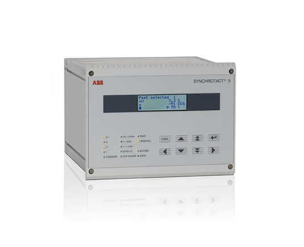
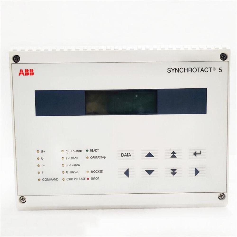
The ABB SYN5201A-Z 3BHB006714R0217 hydraulic servo module is a high-precision drive control unit developed for hydraulic actuators in ABB's industrial control system. It is specifically designed to achieve closed-loop control of hydraulic servo systems for equipment such as steam turbines, water turbines, and large industrial valves. This module integrates high-precision electro-hydraulic conversion, real-time signal feedback, intelligent adjustment algorithms, and multiple safety protection functions. Its core function is to accurately convert electrical signal instructions into hydraulic power output, adjust the displacement, speed, or pressure of the hydraulic actuator by controlling the opening of the servo valve, and collect real-time actuator status signals to achieve closed-loop control. It is widely used in fields such as power, metallurgy, petrochemicals, and water conservancy, and is a key control component to ensure the stable operation of large rotating machinery and industrial valves.
ABB SYN5201A-Z 3BHB006714R0217 Hydraulic Servo Module
Product Overview
The ABB SYN5201A-Z 3BHB006714R0217 hydraulic servo module is a high-precision drive control unit developed for hydraulic actuators in ABB's industrial control system. It is specifically designed to achieve closed-loop control of hydraulic servo systems for equipment such as steam turbines, water turbines, and large industrial valves. This module integrates high-precision electro-hydraulic conversion, real-time signal feedback, intelligent adjustment algorithms, and multiple safety protection functions. Its core function is to accurately convert electrical signal instructions into hydraulic power output, adjust the displacement, speed, or pressure of the hydraulic actuator by controlling the opening of the servo valve, and collect real-time actuator status signals to achieve closed-loop control. It is widely used in fields such as power, metallurgy, petrochemicals, and water conservancy, and is a key control component to ensure the stable operation of large rotating machinery and industrial valves.
Core Basic Parameters
parameter category
Specific content
Product Model
SYN5201A-Z、3BHB006714R0217
manufacturer
ABB Group
Core processor
32-bit industrial grade microcontroller with a main frequency of ≥ 200MHz
controlled object
Electro hydraulic servo valve, hydraulic actuator (oil cylinder/oil motor)
Input control signal
4-20mA or 0-10V DC (switchable through parameter configuration)
Feedback signal type
Displacement sensor signal (4-20mA/LVDT), pressure sensor signal (4-20mA)
Output driving signal
± 40mA current signal (driving servo valve)
control accuracy
Displacement control accuracy ≤± 0.1% FS, velocity control accuracy ≤± 0.5% FS
response time
≤ 5ms (step signal input to output stable)
Proportional gain adjustment range
0.1-10.0 (adaptive adjustment)
power supply voltage
DC 24V ± 15% or DC 48V ± 15%
Working temperature range
-20 ℃~65 ℃ (industrial wide temperature design)
Protection level
IP54 (panel installation), IP20 (cabinet installation)
communication interface
RS485(Modbus-RTU)、PROFINET、CANopen
Installation method
19 inch standard cabinet installation, panel embedded installation
Core functional characteristics
1. High precision electro-hydraulic conversion and closed-loop control
The module adopts ABB's patented "linear amplification+PID adaptive adjustment" technology, which can accurately convert 4-20mA/0-10V control signals into servo valve drive currents, achieving precise control of hydraulic actuator displacement, speed or pressure. By collecting real-time feedback signals from LVDT displacement sensors or pressure sensors, a closed-loop control loop is constructed to automatically compensate for interference factors such as load changes and oil temperature fluctuations. The displacement control accuracy reaches ± 0.1% FS, ensuring stable operation of the actuator at the set value and meeting high-precision control requirements such as turbine control valves and turbine guide vanes.
2. Multi mode control and flexible adaptation
Supports multiple control mode switching, including position control (default), speed control, pressure control, and force control modes, which can be quickly switched through parameter configuration or communication commands to adapt to different types of hydraulic actuators. Built in servo valve linearization compensation algorithm, compatible with ABB and third-party brands' single-stage/two-stage electro-hydraulic servo valves, supporting various feedback components such as LVDT, RVDT, magnetostrictive displacement sensors, etc., without the need for additional adaptation modules, greatly improving system integration flexibility.
3. Comprehensive security protection mechanism
Integrated with multiple software and hardware security protection functions, including overcurrent protection (short circuit/overload of drive circuit), overvoltage/undervoltage protection (abnormal power supply), signal loss protection (triggering safety mode when feedback signal is interrupted), overtravel protection (actuator exceeding limit position), and high oil temperature protection (achieved through external temperature sensors). When an abnormality is detected, the module can trigger protective actions within 5ms, such as outputting safe current, locking control signals, or switching to manual mode, and feedback the fault type through fault codes to maximize the protection of servo valves, actuators, and host equipment safety.
4. Strong anti-interference and high reliability design
Adopting industrial grade reinforced design, the control circuit and power drive circuit are optically isolated, and the signal input and output terminals are equipped with surge suppressors. It has passed the IEC 61000-6-2 industrial electromagnetic compatibility certification and can effectively resist harsh conditions such as strong electromagnetic interference and voltage fluctuations in industrial sites. The core components have undergone high and low temperature cycling, vibration and shock screening, and the average time between failures (MTBF) of the module exceeds 100000 hours, adapting to the strict requirements of continuous operation in industries such as power and metallurgy.
5. Intelligent diagnosis and status monitoring
Equipped with comprehensive self diagnosis and status monitoring functions, it can monitor the internal circuit of the module, servo valve driving status, feedback signal quality, and power supply status in real time, and accurately locate the fault point through fault codes (such as servo valve disconnection, sensor drift). Support real-time monitoring of operating parameters of the executing mechanism (such as displacement fluctuations and response speed), predict equipment degradation trends through trend analysis, issue maintenance warnings in advance, and reduce unplanned downtime.
6. Convenient communication and operation management
Supports multiple industrial communication protocols, seamlessly integrates with DCS systems, PLCs, and equipment monitoring platforms, enabling control command issuance, operation parameter reading, fault information uploading, and remote parameter configuration. Equipped with a 4.3-inch color touch screen, supporting Chinese/English interface switching, operators can intuitively view real-time control curves and fault records, and complete mode switching, parameter calibration, and other operations through panel buttons. Local support for USB interface allows for quick export of historical data and fault reports, facilitating operation and maintenance analysis.
Applicable scenarios
-Power industry: Control of turbine valves in thermal power plants, control of turbine guide vanes/blades in hydropower stations, precise adjustment of steam/water intake to ensure stable unit speed
-Metallurgical industry: Steel plant converter tilting mechanism, continuous casting machine crystallizer vibration table hydraulic servo control to ensure smelting and casting accuracy
-Petrochemical industry: Large scale chemical reactor mixing mechanism, hydraulic control of emergency shut-off valves in pipelines, achieving precise control of process parameters and safety interlocking
-Water conservancy engineering: hydraulic actuator control for reservoir gates and hydropower station discharge valves to ensure safe and stable operation of water conservancy facilities
-Heavy machinery: hydraulic servo control of the pressing mechanism of mining crushers and rolling mills, suitable for precise adjustment requirements under heavy load conditions
-Shipbuilding industry: Hydraulic control of ship propulsion system thrusters and servos to ensure stable ship navigation posture

Precautions for use
1. Before installation, it is necessary to confirm that the module model matches the specifications of the servo valve and the parameters of the actuator. Control signals, feedback signals, and power terminals should be strictly distinguished according to the product manual to avoid module or servo valve damage caused by reverse connection. Strong and weak current circuits should be separately wired and shielded.
2. The installation location should be in a ventilated and dry control cabinet, away from strong electromagnetic interference sources such as high-power inverters and transformers. The ambient temperature should be controlled within the range of -20 ℃ to 65 ℃, avoiding direct sunlight or close to high-temperature heat sources to ensure good module heat dissipation.
Before the first operation, parameter initialization configuration must be completed, including control mode, input/output signal type, proportional gain, stroke limit, etc. The correctness of the control logic must be verified through analog signal testing, and direct connection to the hydraulic system for debugging is prohibited.
4. During operation, it is necessary to regularly check the module's operating status, view control parameters, feedback signals, and fault records through the touch screen, and calibrate the feedback sensor accuracy regularly (recommended once every quarter) to ensure that the control accuracy meets the requirements.
When the oil temperature of the hydraulic system is too high (over 45 ℃), the cooling system should be checked in a timely manner to avoid servo valve jamming or module control accuracy decrease caused by high oil temperature. At the same time, the cleanliness of the hydraulic oil should be checked regularly to prevent impurities from blocking the servo valve.
When a module issues a fault alarm, the relevant equipment should be immediately suspended. The cause should be investigated through fault codes (such as servo valve failure, sensor disconnection). After troubleshooting, a no-load test should be conducted to confirm that the control function is normal before resuming operation.
When performing software upgrades or parameter modifications, it is necessary to first backup the current parameter configuration, ensure stable power supply during the upgrade process, prohibit power interruption, and re verify the control curve after the upgrade is completed to avoid control failure caused by program abnormalities.
8. Fault repair should be carried out by professionals with hydraulic servo system debugging qualifications. Before repair, the module power supply and hydraulic system pressure should be cut off. Non professionals are prohibited from disassembling or modifying internal parameters without authorization.

- User name Member Level Quantity Specification Purchase Date
- Satisfaction :
-


