
Allen Bradley 1336 PLUS II Adjustable Frequency Driver
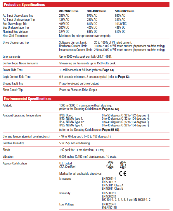
Power outage response: Supports two modes of "line loss fault enable/disable". When there is a line loss, the operation is maintained through DC bus energy storage. When the bus voltage drops to 85% of the rated value, the output is turned off. After power is restored, it can be restarted through methods such as flying start and detecting motor voltage.
3. Monitoring and Diagnosis
Real time monitoring: Display output current, voltage, frequency, temperature and other parameters through HIM's backlight ultra twisted LCD (2 lines x 16 characters), supporting multilingual switching; The "Process Display" mode allows customization of display units and parameter combinations (such as "121.6 In/min" and "2.7AmPs").
Fault recording and diagnosis: Cache the last 4 faults and automatically start the fault diagnosis program upon startup; When there is a malfunction, display a prompt in _plain language_ (such as "Undervolt Fault" or "Overtemp Fault") and report the status through the HIM or SCANPort communication port.
Installation and Wiring Guide
1. Installation requirements
Size and weight: There are significant differences in the size of drivers with different frames (A1-G). Taking IP20 (NEMA Type 1) as an example, A1 frame size is 215.9 × 290.0 × 160.0mm (width × height × depth), weighing 4.31kg; G frame size is 635.0 × 2324.1 × 508.3mm, weighing 453.6kg (please refer to the specific frame size table).
Installation spacing: At least 152.4mm (6 inches) of ventilation space should be reserved on both sides and the back; The F-frame drive requires additional side/back space, and when the open drive is installed in the user housing, it needs to be equipped with two 725 CFM fans (BPR series requires fans of 450 CFM or above).
2. Wiring specifications
Power wiring (TB1 terminal): input terminals R (L1), S (L2), T (L3), output terminals U (T1), V (T2), W (T3), DC bus terminal+DC/- DC, grounding terminals PE (protective ground), TE (shielding ground); 75 ℃ copper wire is required, with different wire diameters for different frame terminals (maximum 5.3mm ²/10AWG for A1-A4 frame, maximum 303.6mm ²/600MCM for G frame), and torque must comply with specifications (such as 1.81N/m/16lb in for A1-A4 frame).
Control and signal wiring:
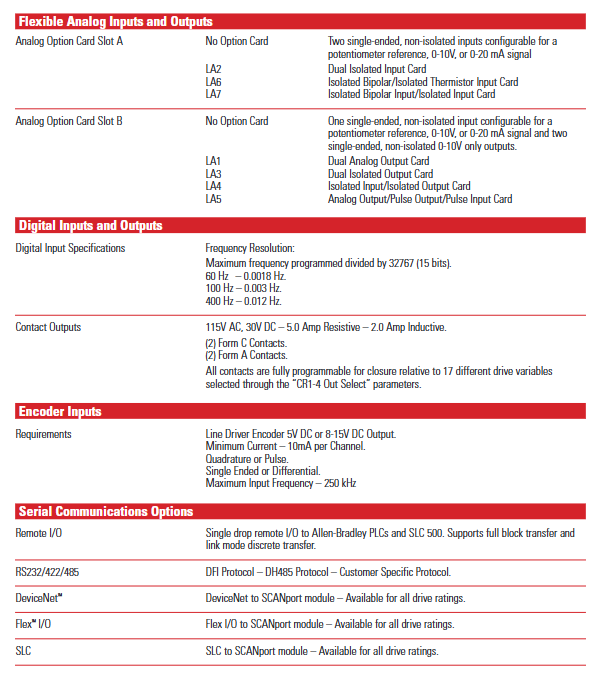
Analog I/O: Standard configuration supports 0-10V/0-20mA input (single ended non isolated), optional LA series isolation card (such as LA2 dual isolated input, LA3 dual isolated output), shielding layer needs to be connected to TE terminal.
The digital I/O: TB3 terminal supports 115V AC/24V AC/DC/TTL level input and can be programmed with functions such as start, stop, reverse, and preset speed selection; The output contacts (CR1-CR4) support 115V AC/30V DC, 5A resistive/2A inductive loads.
Encoder wiring: Supports 5V DC/8-15V DC line driven encoder (orthogonal or pulse signal), maximum input frequency 250kHz, single ended/differential signal can be used, and the shielding layer is connected to the TE terminal.
Selection and Configuration
1. Selection Guide
Model interpretation: The complete model format is "1336F-XXXXXX-XX", such as "1336F-B020-AA", where "B" represents the voltage/power code (460V, 20HP), "020" represents the power level, and "AA" represents the protection level (IP20/NEMA Type 1).
Load adaptation: The selection of constant torque (CT) and variable torque (VT) loads needs to be distinguished, for example, the 460V B020 model, CT rated 20HP, VT rated 25HP; the corresponding model needs to be selected according to the actual load type (such as CT for conveyor belt and VT for fan).
Option configuration: Supports factory pre installation or on-site installation options, such as communication cards (GM1 single node RIO, GM5 DeviceNet), control interface cards (L4 contact closed, L5 24V AC/DC), HIM (HA1 analog potentiometer, HJ2 digital potentiometer), braking units, reactors, etc.
2. Capacity reduction guide
When the operating conditions of the drive exceed the rated range, it is necessary to reduce the capacity. The core scenarios for reducing the capacity include:
Altitude: When it exceeds 1000m, the capacity decreases by about 6% for every 1000m increase (refer to Figure AD).
When the ambient temperature exceeds 40 ℃, the capacity will decrease by about 2% for every 1 ℃ increase (refer to Figure A-AC).
Carrier frequency: When it exceeds 4kHz (some models are 2kHz), the amplitude should be increased and the capacitance should be reduced according to the frequency (such as reducing the capacitance by 10% at 6kHz).
Fault handling and maintenance
1. Common faults and troubleshooting
The document lists more than 40 types of fault codes, and the core faults and their handling methods are as follows:
Fault code, fault name, cause analysis, and handling suggestions
04 Under voltage fault: Input voltage too low, bus capacitor fault, power failure. Check input voltage, replace capacitor, and confirm power stability
05 Overvoltage fault: Input voltage too high, brake unit fault, high load regeneration energy. Check input voltage, repair brake unit, and increase regeneration resistance
- OMRON
- ABB
- General Electric
- EMERSON
- Honeywell
- HIMA
- ALSTOM
- Rolls-Royce
- MOTOROLA
- Rockwell
- Siemens
- Woodward
- YOKOGAWA
- FOXBORO
- KOLLMORGEN
- MOOG
- KB
- YAMAHA
- BENDER
- TEKTRONIX
- Westinghouse
- AMAT
- AB
- XYCOM
- Yaskawa
- B&R
- Schneider
- KONGSBERG
- NI
- WATLOW
- ProSoft
- SEW
- ADVANCED
- Reliance
- TRICONEX
- METSO
- MAN
- Advantest
- STUDER
- DANAHER MOTION
- Bently
- Galil
- EATON
- MOLEX
- DEIF
- B&W
- ZYGO
- Aerotech
- DANFOSS
- Beijer
- Moxa
- Rexroth
- Johnson
- WAGO
- TOSHIBA
- BMCM
- SMC
- HITACHI
- HIRSCHMANN
- Application field
- XP POWER
- CTI
- TRICON
- STOBER
- Thinklogical
- Horner Automation
- Meggitt
- Fanuc
- Baldor
- SHINKAWA
- Other Brands
- UniOP
- KUKA
- Iba
- Beckhoff
-
 Basler DECS-200-2L Digital Excitation Control
 -
 Basler BE1-47N Voltage Phase Sequence Relay
 -
 Basler AEC63-7 Analog Excitation Controller 220-277V
 -
 Basler BE1-50/51B-107 Overcurrent Relay
 -
 Basler Electric BE1‑32R BE1‑E1P‑BON0F Protective Relay
 -
 Basler BE1-25 Solid State Time Overcurrent Relay M1EA6PA5S1F
 -
 Basler MVC 232 Manual Voltage Control Module 90 37000 103 60VAC 55VDC
 -
 Basler RAL6144-16GM Racer GigE Line Scan Camera
 -
 Basler SSR 63-12 Static Voltage Regulator
 -
 Basler BE1-51A Overcurrent Relay
 -
 Basler BE1-87T Solid State Protective Relay
 -
 Basler SR4A2B01B3A Static Voltage Regulator
 -
 Basler SSR 32-12 Static Voltage Regulator
 -
 Basler TRR00696 Transformer 1KVA 115V
 -
 Basler DECS-100-B15 AVR Replacement
 -
Basler BE1-27 Under-Voltage Relay
-
 Basler ACA2000-50GM Interface Module
 -
 Basler AEC63-7 Analog Excitation Controller
 -
 Basler PRS 250 Veri-Sync Relay
 -
 Basler SR4A-2B15B3A Static Voltage Regulator
 -
Basler BE1-32R Power Relay
-
Basler SR8A-2B06B3E Static Voltage Regulator
-
Basler BE1-81 O/U Frequency Relay
-
 Basler BE1-51A-K2E-W6M-B1N0F Overcurrent Relay
 -
Basler BE1-851 Overcurrent Relay G3A1S1 – 48-125V AC/DC
-
 Basler BEI-51 Overcurrent Relay – NSN 5945-01-293-2363
 -
Basler Electric L301KC Protective Relay – L301KC
-
 Basler DECS-100-B15 Automatic Voltage Regulator – Generator AVR
 -
 Basler SR4A-2B15B3A Static Voltage Regulator – SR4A2B15B3A
 -
 Basler UF 312 Under Frequency Protective Module – 9094700100
 -
Basler Electric MVC 232 Manual Control Module – 60VAC 55VDC 20A
-
Basler PRS 250 Veri-Sync Relay – Generator Synchronizing Relay
-
 Basler DECS-100-A05 Digital Regulator Review
 -
 Basler AEM-2020 Analog Expansion Module Specs
 -
 Basler DECS-100-B15 Digital Excitation Specs
 -
Basler Electric 9125600106 Regulator Component
-
Basler BE1-51A-K1E-W6M-B1N0F Overcurrent Relay
-
 Basler MVC-301 MVC 300 Excitation Controller
 -
 Basler SSR 32-12 Static Voltage Regulator
 -
 Basler 9-2849-00-101 Control Module
 -
Basler BE1-51A Overcurrent Relay
-
 Basler BE1-51/27R Overcurrent Relay
 -
 Basler BE1-51 Overcurrent Relay
 -
 Basler SR8A-2B15B3A Static Voltage Regulator
 -
 Basler BE32965001 Transformer and Timer Board
 -
 Basler 9174700100 EL200-7 Excitation Limiter
 -
 Basler BE2000E AVR Voltage Regulator
 -
Basler BE1-87G Differential Relay
-
 Basler BE21834001 Generator Control Module
 -
Basler DECS-100-B15 AVR
-
 Basler D90 96801 100 PCB Card
 -
 Basler XR2002F Voltage Regulator (110 VAC, 48-480 Hz)
 -
 Basler SR8A-2B14B3A Regulator
 -
 Basler 9561500100 Module
 -
 Basler DECS-400 BE1-11 System
 -
 Basler DECS-100-B15 Excitation Control
 -
 Basler SCP 210 Frequency Controller
 -
Basler SR4A-2B15B3A Static Voltage Regulator
-
Basler BE1-32R Power Relay
-
 Basler PIA2400-17GM Power Interface Adapter
 -
 Basler MVC 232 Manual Voltage Control Module
 -
 Basler SSR 32-12 Static Voltage Regulator
 -
Basler 5MW AVR Generator Voltage Regulator
-
 Basler VR63-4B Voltage Regulator
 -
Basler DECS-100-A05 AVR for Engine Generator
-
Basler DECS-100-B15 Automatic Voltage Regulator
-
Basler BE1-32R Directional Power Relay
-
Basler BE1-87B Differential Relay
-
 Basler UFOV 260A Protective Module
 -
 Basler 9-2614-02-100 PCB Rev M
 -
Basler DECS-100-B15 Digital AVR
-
 Basler 9284900103 PS DECS-400N
 -
 Basler D4N3H1U Intertie Protection
 -
 Basler DECS-100-B15 A15 AVR
 -
 Basler KR4F Voltage Regulator
 -
 Basler BE26434 T14 Transformer
 -
 Basler SR8A-2B15B3A Regulator
 -
 Westinghouse 774B472A12 AR Relay
 -
Basler DECS-100-B15 AVR
-
Basler XR2002F Regulator 110V
-
Basler SR125-E Static Regulator
-
Basler SSR 125-12 Regulator
-
Basler MOC2599 Motor Pot
-
 Basler BE1-DFPR Feeder Relay
 -
 Basler CBS 305 Current Boost
 -
Basler BE1-25 AutoSync
-
Basler MVC 300 Voltage Control
-
 Basler BE3-25A AutoSync
 -
 Basler KR7FF Static Regulator
 -
Basler 90-49000-100 Regulator
-
 Basler 880 kVA Dry Type Transformer Specs
 -
Basler Electric BE1-25 Sync-Check Relay Specs
-
 Basler SSR 125-12 Voltage Regulator Specs
 -
 Basler Electric BE1-851 Overcurrent Relay Review
 -
Basler Electric 149D930G02 Control Sub-Assembly
-
 Basler Electric BE1-81O/UT Frequency Relay Specs
 -
 Basler Electric BE1-51/27C Overcurrent Relay
 -
 Basler Electric 149D956G02 Industrial Component
 -
Basler Electric BE1-51A Overcurrent Relay Specs
-
 Basler Electric BE1-40Q Loss of Excitation Relay
 -
Basler DECS-200 Excitation Control System
-
 Basler DECS-200 Voltage Regulator 56-277V AC / 125V DC
 -
Basler BE1-87T Transformer Differential Relay
-
 Basler RDP-110-S1 Protection Relay
 -
 Basler BE1-700V Digital Protective Relay
 -
 Basler BE1-951 Overcurrent Protection System
 -
 Basler DECS-300 Digital Excitation Control
 -
 Basler DECS-200 Digital Excitation Control
 -
 Basler DECS-200-1C Excitation Control System
 -
Basler DECS-200-1L Digital Excitation Control
-
 Basler Electric BE1-GPS Generator Protection System
 -
Basler Electric DECS-200-1C Digital Excitation Controller
-
 Basler Electric DECS125-15 Excitation Control with Power Module
 -
Basler Electric BE1-87G Differential Relay
-
 Basler Electric BE1-11 Protection System I5A3M2P2N0EA00
 -
Basler Electric DECS-200-1C Excitation Control System
-
Basler Electric BE1-11g Generator Protection Relay
-
Basler Electric DECS 125-15-B2C1 V2.0.9 Excitation Control
-
Basler Electric BE1-81O/UT3ED1JA7N2F Frequency Relay
-
Basler Electric BE1-81O/UT3EE1YB7N1F Frequency Relay
-
 Basler Electric DECS-200-1L Digital Excitation Control System
 -
Basler DECS125-15-B2C1 Excitation Control
-
 Basler 9507900205 SSR Retrofit Voltage Regulator
 -
 Basler BE2000E Digital Voltage Regulator
 -
 Basler BE1-GPS Generator Protection System
 -
Basler DECS-250-CN1CN1N Digital Excitation Control
-
 Basler DGC-2020 Genset Controller
 -
Basler BE1-81O UT3ED1LA7N0F Frequency Relay (Variant)


