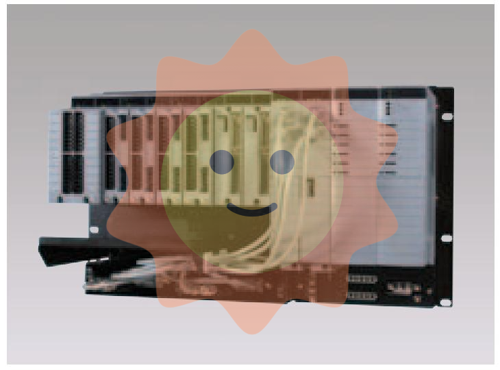
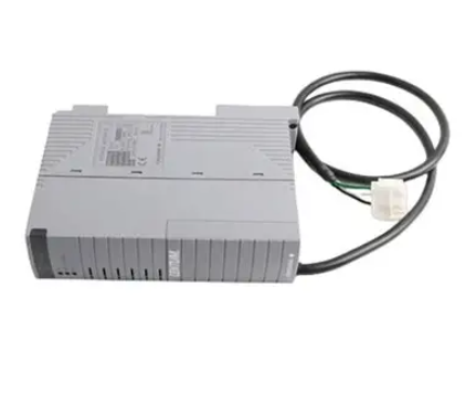
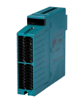
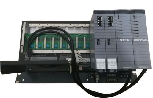
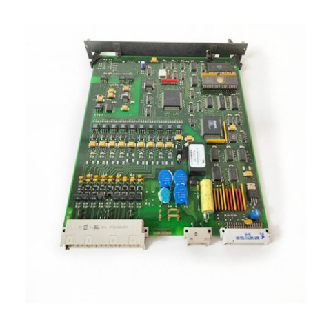
GE SPU232.1-CAN (part number: 029.354 630, hereinafter referred to as "CAN Communication Industrial Module") is a high-performance embedded module developed by General Electric (GE) for the data communication needs in the field of industrial automation. It is based on CAN bus technology and has serial communication functions. It is designed specifically for device interconnection, data transmission, and command interaction in industrial environments. As a "communication hub" in industrial control systems, this module can achieve real-time data exchange and protocol conversion between different devices. With industrial grade stability, anti-interference ability, and flexible configuration characteristics, it is widely used in scenarios such as intelligent manufacturing, rail transit, energy and chemical engineering that require extremely high communication reliability. Its compact structural design is suitable for standard industrial cabinets, and is compatible with GE's full range of automation control equipment and third-party mainstream industrial equipment, effectively reducing the difficulty of system integration and improving overall communication efficiency and stability.
GE SPU232.1-CAN PART NO: 029.354 630. Industrial grade module
Product Overview
GE SPU232.1-CAN (part number: 029.354 630, hereinafter referred to as "CAN Communication Industrial Module") is a high-performance embedded module developed by General Electric (GE) for the data communication needs in the field of industrial automation. It is based on CAN bus technology and has serial communication functions. It is designed specifically for device interconnection, data transmission, and command interaction in industrial environments. As a "communication hub" in industrial control systems, this module can achieve real-time data exchange and protocol conversion between different devices. With industrial grade stability, anti-interference ability, and flexible configuration characteristics, it is widely used in scenarios such as intelligent manufacturing, rail transit, energy and chemical engineering that require extremely high communication reliability. Its compact structural design is suitable for standard industrial cabinets, and is compatible with GE's full range of automation control equipment and third-party mainstream industrial equipment, effectively reducing the difficulty of system integration and improving overall communication efficiency and stability.
Specification parameters
2.1 Basic Parameters
-Product model: SPU232.1-CAN; Part number: 029.354 630
-Product type: Industrial grade CAN/RS-232 dual-mode communication module
-Core protocol: CAN 2.0A/B protocol, supporting standard frames and extended frames; RS-232 protocol
-Size specifications: 2U standard industrial size (88.9mm × 150mm × 50mm), compatible with 19 inch standard cabinets
-Weight: Approximately 0.9kg
-Installation method: rail installation or cabinet screw fixation
2.2 Electrical Parameters
-Power supply voltage: DC 24V ± 20% (wide voltage design, compatible with commonly used industrial power sources)
-Working current: ≤ 300mA during normal operation, peak current ≤ 500mA (communication emergency state)
-Power consumption: Typical power consumption ≤ 7.2W, maximum power consumption ≤ 12W
-Isolation voltage: 2500V DC (1 minute) between the power supply terminal and the signal terminal, photoelectric isolation of the CAN bus interface
-Electromagnetic compatibility: Complies with EN 61000-6-2 (immunity) and EN 61000-6-4 (emission) industrial standards
2.3 Communication Parameters
-CAN interface: 2-channel independent CAN bus interface, supporting CAN FD (optional), communication speed adjustable from 5kbps to 1Mbps; Adopting DB9 or terminal block interface, supporting bus terminal resistance configuration (120 Ω optional)
-RS-232 interface: 1 standard RS-232 interface, baud rate adjustable from 300bps to 115200bps, data bits 7/8, stop bits 1/2, supports odd parity, even parity, and no parity
-Data cache: Built in 4KB CAN receive cache and 2KB send cache, 1KB RS-232 data cache to avoid data loss
-Protocol conversion: Supports bidirectional conversion between CAN and RS-232 protocols, with customizable data mapping rules
2.4 Environmental Parameters
-Working temperature: -40 ℃~+85 ℃ (wide temperature range, suitable for extreme industrial environments)
-Storage temperature: -55 ℃~+100 ℃
-Relative humidity: 10%~95% (no condensation, in accordance with IEC 60068-2-3 standard)
-Vibration protection: Complies with IEC 60068-2-6 standard, 10Hz-2000Hz, acceleration 10g
-Impact protection: Complies with IEC 60068-2-27 standard, peak acceleration 50g, duration 6ms
-Protection level: IP20 (module body), IP40 (optional with protective shell)
Performance characteristics
3.1 Dual Mode Communication and Flexible Conversion
The module integrates dual communication interfaces of CAN and RS-232, supporting bidirectional data transparent transmission and custom conversion of both protocols, which can easily solve the interconnection problem between old RS-232 devices and new CAN bus systems in industrial sites. By using supporting software, data filtering rules, frame format conversion parameters, and communication rates can be configured to meet the communication needs of different scenarios without the need for additional protocol conversion programs, reducing integration costs.
3.2 Industrial grade high reliability design
Using industrial grade high anti-interference components, the CAN interface is equipped with built-in photoelectric isolation and surge protection circuits, which can effectively resist electromagnetic interference, voltage fluctuations, and electrostatic shocks in industrial sites, ensuring stable communication links. The module supports the "heartbeat packet" mechanism, which can monitor the status of the communication link in real time. When abnormalities such as disconnection or error occur, an alarm signal is immediately triggered and a fault log is recorded for quick troubleshooting.
3.3 Efficient Data Processing and Caching
Equipped with a high-performance 8-bit microprocessor, the data processing speed can reach 1Mbps, supporting concurrent reception and forwarding of CAN bus multi node data. It has data frame filtering and priority sorting functions, and can prioritize the processing of emergency control instructions (such as equipment shutdown signals). Built in large capacity data cache area, which can temporarily store critical data during communication peaks or when devices are temporarily offline, avoiding data loss and ensuring system data integrity.
3.4 Convenient Configuration and Operation
Support parameter configuration through RS-232 interface or supporting upper computer software (compatible with Windows/Linux system), including communication rate, protocol rules, alarm thresholds, etc. The configuration parameters can be saved locally and will not be lost after power failure. The module panel is equipped with LED indicator lights (power light, CAN communication light, RS-232 communication light, fault light), which can intuitively display the operating status of the equipment, making it easy for on-site operation and maintenance personnel to quickly judge the working condition of the equipment.
3.5 Strong environmental adaptability and durability
Adopting a fully metal shell and sealed circuit design, it has good heat dissipation performance and dust and oil pollution prevention capabilities, and can operate stably for a long time in industrial sites with high temperature, low temperature, high humidity, and high dust. Through rigorous industrial environment reliability testing, including high and low temperature cycling testing, vibration and shock testing, electromagnetic compatibility testing, etc., we ensure that we meet the requirements of various harsh industrial scenarios.
Working principle
The GE SPU232.1-CAN module is based on a microprocessor and utilizes a CAN controller and RS-232 transceiver to achieve physical layer and data link layer processing for two communication protocols. Its workflow mainly includes five steps: parameter initialization, data reception, protocol conversion, data transmission, and status monitoring
1. Parameter initialization: After the module is powered on, it first executes a self-test program to detect the core circuit, interface status, and cache availability. After passing the self-test, it loads preset configuration parameters (such as CAN communication rate, RS-232 baud rate, data filtering rules, etc.), completes initialization, and enters standby mode, waiting for data transmission requests.
2. Data reception: When data is transmitted through the CAN bus or RS-232 interface, the corresponding transceiver converts the analog signal into a digital signal and transmits it to the microprocessor. The microprocessor determines the source and type of data according to preset rules, verifies the data (such as CAN frame CRC check, RS-232 parity check), and temporarily stores the data in the corresponding cache area after passing the verification. If the verification fails, the data is discarded and an error message is recorded.
3. Protocol conversion: After the microprocessor reads the cache data, it performs format conversion according to the configured protocol conversion rules (such as converting RS-232 ASCII code data to CAN bus binary data frames, or vice versa), and adds corresponding protocol identifiers (such as CAN frame ID, RS-232 address code) to the converted data to ensure that the receiving end can correctly recognize the data.
4. Data transmission: After the converted data packet is prioritized by the microprocessor, it is sent to the target device through the corresponding communication interface. If sent via the CAN bus, the CAN controller encapsulates the data frame into a format that complies with the CAN 2.0A/B protocol and sends it to the designated node via the bus; If sent via RS-232, the digital signal will be converted into an analog signal by the RS-232 transceiver and transmitted to the docking device.
5. Status monitoring: During the working process, the microprocessor monitors the signal quality, data transmission error rate, and its own working status (such as power supply voltage, temperature) of the communication link in real time. When communication interruption, error rate exceeding the standard, voltage abnormality and other faults are detected, the panel fault indicator light is immediately lit, and an alarm signal is sent through the preset interface. At the same time, the fault information is written into the local log for subsequent troubleshooting.
Precautions
5.1 Installation precautions
-Before installation, it is necessary to confirm whether the module model and component number are consistent with the system requirements to avoid communication failures caused by model mismatch.
-The module should be installed in a well ventilated location away from strong electromagnetic interference sources such as frequency converters and high-power motors, and kept at least 10cm away from high-temperature equipment such as heaters to prevent heat from affecting module performance.
-When installing the guide rail, it is necessary to ensure that the guide rail model matches. When fixing the screws, the torque should be controlled at 0.5-0.8N · m to avoid damaging the module housing due to over tightening or loosening the module.
-The CAN bus wiring should use shielded twisted pair cables, and 120 Ω terminal resistors should be configured at both ends of the bus. The wiring length should not exceed 1000m (at a communication rate of 1Mbps) to avoid signal attenuation or interference.
5.2 Wiring and Operation Precautions
-Before wiring, all power supplies must be disconnected. The positive and negative poles and signal pins of the CAN interface and RS-232 interface should be distinguished, and the module wiring diagram should be strictly followed to avoid interface burnout caused by reverse connection.
-The power supply should have overcurrent protection function, and the output voltage should be stable within the range of 24V ± 20% to avoid voltage fluctuations that may cause module restart or damage.
-During operation, it is not allowed to randomly plug or unplug communication cables or modify configuration parameters. If reconfiguration is required, the module data transmission must be stopped first to avoid data loss or bus conflicts.
-When the module fault light is on, it is necessary to first investigate the power supply and wiring issues, and then read the fault log through the upper computer software. It is not allowed to directly disassemble the module for maintenance.
5.3 Maintenance and Storage Precautions
-Regular maintenance (recommended once a month) is required to check whether the module wiring is loose and whether the indicator light status is normal. When cleaning the surface dust of the module, a dry soft cloth should be used, and corrosive cleaning agents such as wet cloth or alcohol should not be used.
-When the module is not used for a long time, it should be stored in a dry, ventilated, and non corrosive gas environment, packaged in an anti-static bag, avoiding direct sunlight and severe collisions, and stored at a temperature controlled between -55 ℃ and+100 ℃.
-Module maintenance must be carried out by professional technicians authorized by GE. It is prohibited to disassemble modules or replace components by oneself, otherwise it will lose the product warranty qualification and may cause safety hazards.
-It is recommended to conduct a comprehensive inspection of the module every six months, including communication rate testing, data transmission error rate testing, and anti-interference performance testing, to ensure that the module is in good working condition.
Application scenarios
The GE SPU232.1-CAN module, with its dual-mode communication, high reliability, and strong environmental adaptability, is widely used in various industrial automation scenarios and has become a core component for connecting different communication protocol devices. Its main application areas include:
6.1 Intelligent Manufacturing Production Line
In production lines such as automobile manufacturing and electronic component assembly, it is used to connect old RS-232 interface devices (such as barcode scanners and small sensors) with new CAN bus control systems (such as PLCs and industrial robots), to achieve real-time collection of production data and accurate issuance of control instructions, ensuring the coordinated work of various equipment in the production line, and improving production efficiency and product qualification rate.
6.2 Control of Rail Transit Vehicles
In the vehicle control systems of subways and high-speed trains, as a communication relay module for equipment inside the carriage, it connects CAN bus control units (such as traction systems and braking systems) with monitoring devices (such as temperature sensors and pressure sensors) with RS-232 interfaces to transmit real-time vehicle operating parameters and fault information, ensuring the safety of vehicle operation, and supporting remote diagnosis of vehicle equipment by ground maintenance systems.
6.3 Energy and Chemical Monitoring System
In monitoring systems for petrochemical and natural gas extraction scenarios, RS-232 interface instruments (such as flow meters and level gauges) are used to connect with CAN bus industrial Ethernet gateways on site. Key parameters during the production process (such as flow rate, pressure, and temperature) are uploaded in real time to the central monitoring platform, and control instructions are received from the platform to achieve automated monitoring and remote control of the production process.
6.4 Intelligent Warehousing and Logistics Equipment
In automated three-dimensional warehouses and AGV (Automated Guided Vehicle) systems, as the communication bridge between AGV and warehouse management systems, the CAN bus devices on AGV (such as drive systems and navigation sensors) exchange data with the warehouse management system through the RS-232 interface of modules, completing functions such as AGV path planning, receiving cargo handling instructions and feedback on execution status, and improving the automation level of warehousing and logistics.
6.5 Agricultural and Environmental Monitoring Equipment
In intelligent agricultural irrigation systems and environmental monitoring stations, environmental sensors (such as temperature and humidity sensors, soil sensors) connected to RS-232 interfaces and CAN bus data collectors are used to transmit monitoring data in real time to the data center, achieving automatic start stop of irrigation equipment and remote monitoring of environmental parameters, suitable for long-term stable operation in harsh outdoor environments.
- User name Member Level Quantity Specification Purchase Date
- Satisfaction :
-


