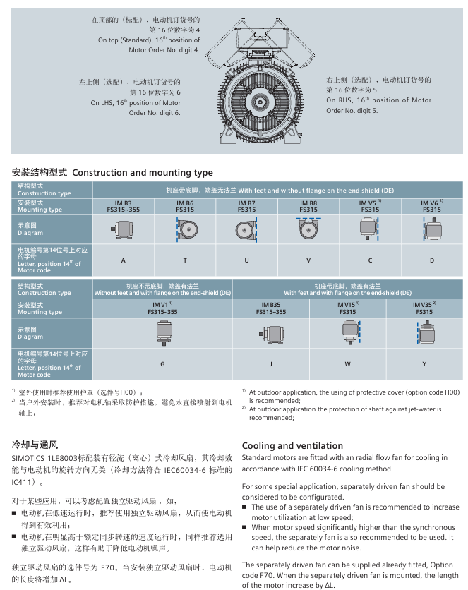
SIEMENS SIMOTICS 1LE8 series low-voltage high-power motor
Comparison dimension 1LE8003 (universal type) 1LE8033 (frequency conversion specific type)
Answer: The bearing configuration is divided into standard and enhanced schemes, and the selection needs to match the size of the cantilever force at the shaft end (such as the load on the pulley and coupling):
Bearing configuration type:
Applicable scenarios for configuration scheme: Bearing type (drive end/non drive end) Maximum allowable cantilever force (example: 315 machine base 4-pole, N)
Standard solution (default) for ordinary loads (such as coupling transmission), deep groove ball bearings (6319 C4/6319 C4) with radial 7850N and axial 9290N (horizontal installation)
Enhancement scheme (L22) for high cantilever force (such as belt drive) cylindrical roller bearings (NU319/6319 C4) with radial lifting of 30%~50% (specific details need to be checked in the selection table)
Insulation scheme (L27) Frequency conversion scenario (anti stray current) Insulation deep groove ball bearing (INS. 6319 C4/...) Same as standard scheme, adding insulation layer
Selection logic:
Step 1: Calculate the actual cantilever force F Q=C × F U, where F U=2 × 10 7 × P/(n × D) (P is the rated power kW, n is the speed rpm, D is the pulley diameter mm), and C is the preload coefficient (flat belt=2, V-belt=2-2.5); Step 2: Compare the calculated value with the maximum allowable cantilever force of the standard solution: If F Q ≤ the standard value, choose the standard solution (no additional configuration required); If F Q>standard value, choose the enhancement scheme (L22) (replace the cylindrical roller bearing at the driving end);
If it is a frequency conversion scenario, regardless of the magnitude of the cantilever force, an insulation scheme (L27) should be added to avoid damage to the bearings caused by stray currents.
Example: The 315 base 4-pole motor drives a V-belt pulley (D=200mm) with a rated power of 250kW and a speed of 1490rpm,
F U=2 × 10 7 × 250/(1490 × 200) ≈ 1678NF Q=2.5 × 1678 ≈ 4195N < standard value 7850N, choose the standard solution.

- ABB
- General Electric
- EMERSON
- Honeywell
- HIMA
- ALSTOM
- Rolls-Royce
- MOTOROLA
- Rockwell
- Siemens
- Woodward
- YOKOGAWA
- FOXBORO
- KOLLMORGEN
- MOOG
- KB
- YAMAHA
- BENDER
- TEKTRONIX
- Westinghouse
- AMAT
- AB
- XYCOM
- Yaskawa
- B&R
- Schneider
- Kongsberg
- NI
- WATLOW
- ProSoft
- SEW
- ADVANCED
- Reliance
- TRICONEX
- METSO
- MAN
- Advantest
- STUDER
- KONGSBERG
- DANAHER MOTION
- Bently
- Galil
- EATON
- MOLEX
- Triconex
- DEIF
- B&W
- ZYGO
- Aerotech
- DANFOSS
- Beijer
- Moxa
- Rexroth
- Johnson
- WAGO
- TOSHIBA
- BMCM
- SMC
- HITACHI
- HIRSCHMANN
- Application field
- XP POWER
- CTI
- TRICON
- STOBER
- Thinklogical
- Horner Automation
- Meggitt
- Fanuc
- Baldor


