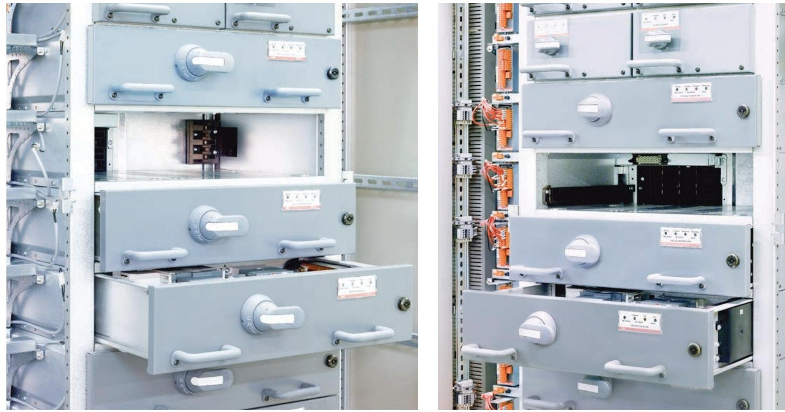
ABB MNS iS Motor Control Center System
Monitoring level: Integrated MView local human-machine interface and web server, supporting remote access and configuration.
2. Key communication components
Component Function Description
MControl has a built-in communication interface that supports real-time data exchange with MStart modules (current, temperature, status, etc.) and can be directly connected to Profibus DP/Profinet networks.
As a system gateway, MLink supports protocols such as Profibus DP, Profinet, Modbus RTU/TCP, OPC, etc., enabling integration with PLC, SCADA and other systems, while also providing web server functionality.
MView local touch panel (optional), displaying motor status, alarm information, and operation buttons based on a web interface, supporting permission management.
Communication Protocol and Interface
1. Supported protocol types
Industrial bus protocol:
Profibus DP/DP V1 (slave mode, supporting process data and diagnostic information transmission);
Profinet I/O (compatible with ABB systems and supports real-time communication);
Modbus RTU (serial communication) and Modbus TCP (Ethernet communication).
General Agreement:
Built in web server, supporting access to monitoring interface through standard browsers;
OPC interface, easy to integrate with third-party SCADA or MES systems;
NTP (Network Time Protocol) enables system wide time synchronization.
2. Data transmission capability
Internal communication: A 10 Mbps real-time bus is used between MControl and MLink, with a command response time of approximately 2 ms for a single MControl and a total system response time of ≤ 258 ms for 60 nodes.
External interaction:
The maximum transmission rate of Profibus DP is 12 Mbps;
Profinet and Modbus TCP support 100 Mbps Ethernet transmission;
Support data block read and write (such as motor current, temperature, tripping reasons, etc.) and remote control commands (start/stop/reset).

System integration capability
1. Integration with upper level systems
Process Control System (PCS): Using MLink as a gateway, the motor status and measurement values (current, power, energy consumption) are uploaded to PLC or DCS, and control instructions are received to achieve remote operation.
Electrical network monitoring system: supports sending electrical parameters (such as harmonics and power factor) to the energy management system (EMS) to assist in energy optimization.
Maintenance management system: Push equipment health data (contactor action frequency, operating hours, temperature trend) to CMMS (computerized maintenance management system) through OPC interface, supporting the development of predictive maintenance plans.
2. Redundancy and reliability design
Dual redundant communication: supports two independent communication paths (primary/backup MLink). When the primary link fails, it automatically switches to the backup link to ensure uninterrupted operation, with a switching time of ≤ 100 ms.
Communication fault protection: Configure the "fail safe" mode (such as keeping the motor running/stopping in case of communication interruption) to avoid unexpected shutdowns caused by network issues.
Time synchronization and data consistency
Synchronization mechanism: Implement system wide time calibration through NTP protocol, support access to factory level time servers (such as GPS synchronization sources), and ensure that the timestamp accuracy of event records (alarms, trips) is ≤ 1 ms.
Data timeliness: The update cycle of key measurement values (such as current and temperature) can be configured (default 100 ms) to meet real-time monitoring requirements; Historical data (energy consumption, number of actions) is stored at the minute level and supports trend analysis.

- ABB
- General Electric
- EMERSON
- Honeywell
- HIMA
- ALSTOM
- Rolls-Royce
- MOTOROLA
- Rockwell
- Siemens
- Woodward
- YOKOGAWA
- FOXBORO
- KOLLMORGEN
- MOOG
- KB
- YAMAHA
- BENDER
- TEKTRONIX
- Westinghouse
- AMAT
- AB
- XYCOM
- Yaskawa
- B&R
- Schneider
- Kongsberg
- NI
- WATLOW
- ProSoft
- SEW
- ADVANCED
- Reliance
- TRICONEX
- METSO
- MAN
- Advantest
- STUDER
- KONGSBERG
- DANAHER MOTION
- Bently
- Galil
- EATON
- MOLEX
- DEIF
- B&W
- ZYGO
- Aerotech
- DANFOSS
- Beijer
- Moxa
- Rexroth
- Johnson
- WAGO
- TOSHIBA
- BMCM
- SMC
- HITACHI
- HIRSCHMANN
- Application field
- XP POWER
- CTI
- TRICON
- STOBER
- Thinklogical
- Horner Automation
- Meggitt
- Fanuc
- Baldor
- SHINKAWA
- Other Brands


