
Bender LifeGuard ® LG2 series protective panel
Bender LifeGuard ® LG2 series protective panel
Product Overview
Bender LifeGuard ® The LG2 series is an industrial grade ground fault protection panel launched by Bender, a German company. Its core function is to monitor the ground fault current in the circuit, quickly cut off the load power supply when the current reaches the trip threshold, and avoid safety risks such as electric shock and arc flashover. The product is compatible with various voltage and phase industrial circuits, providing flexible installation forms and operation methods, complying with UL 508A industrial control panel standards, and widely used in factory equipment, industrial control systems, and other scenarios.
Core parameters and specifications
Category specific parameters
Adaptation voltage 120VAC、208VAC、208/120VAC、240/120VAC、480VAC、480/277VAC、600VAC、600/347VAC
Circuit phase 1ph (2w/3w), 3ph (3w/4w)
Rated current < 100A, 100A
Release level digital display fixed 6mA
Shell type NEMA 4X polycarbonate, NEMA 4X stainless steel, backplate only (requires self provided cabinet)
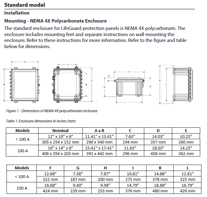
Dimensions (length × width × depth) < 100A: 305 × 254 × 152mm (12 "× 10" × 6 "); 100A: 406 × 356 × 203mm (16" × 14 "× 8")
The wire requirement is only copper wire; Rated at 60 ℃ (140 ℉) or above for<100A; 100A requires a rated temperature of 75 ℃ (167 ℉) or above
Installation and wiring specifications
(1) Installation requirements
Installation of shell:
Provide wall mounted mounting feet and follow separate wall mounting instructions;
It is recommended to use NEMA 4X or higher grade connectors at the bottom of the casing for cable perforation to maintain the protection level.
Only for backplate installation:
It needs to be installed in a compliant cabinet, with vertical clearance requirements of 152mm (6 ") for<100A and 203mm (8") for 100A;
Fix with 4 # 10 screws, with a mounting hole diameter of 6.4mm (1/4 ").
(2) Wiring rules
Installation must be carried out by licensed electricians, following local, state, and national electrical regulations;
All active conductors (including neutral wire N) need to pass through a current transformer and be connected to the incoming side of the contactor;
Connect the load or protected branch to the outgoing side of the contactor;
The incoming and load grounding wires must be connected to the backplane grounding terminal and must not pass through the current transformer;
The number of conductors and wiring diagrams corresponding to different voltages are as follows:
Reference wiring diagram for voltage specification, number of conductors (excluding grounding)
120 VAC 1ph/2w(L1、N) Figure W1
208 VAC 3ph/3w(L1、L2、L3) Figure W2
208/120 VAC 3ph/4w(L1、L2、L3、N) Figure W3
240/120 VAC 1ph/3w(L1、L2、N) Figure W4
480 VAC 3ph/3w(L1、L2、L3) Figure W2
480/277 VAC 3ph/4w(L1、L2、L3、N) Figure W3
600 VAC 3ph/3w(L1、L2、L3) Figure W2
600/347 VAC 3ph/4w(L1、L2、L3、N) Figure W3
Operation process and functions
(1) Basic operation (non digital version)
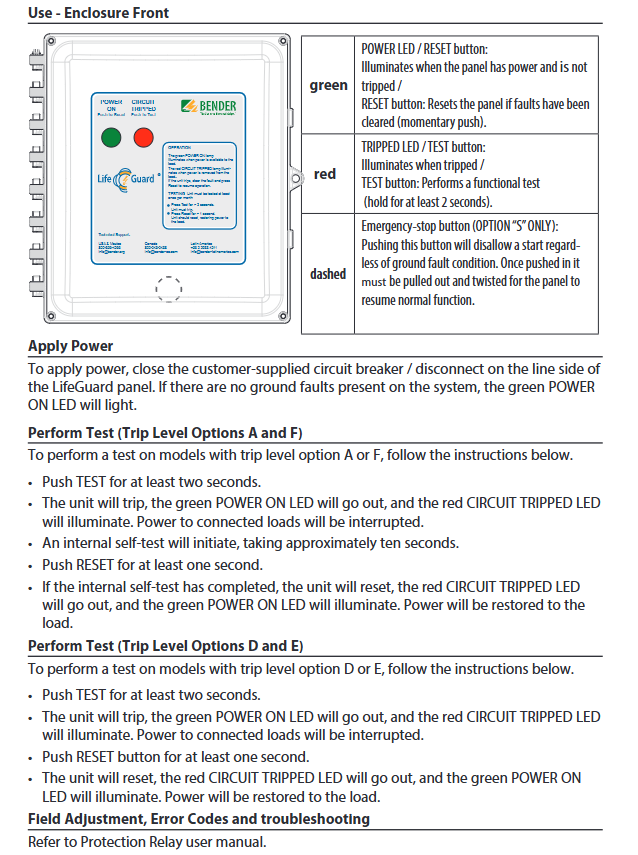
Power on: Close the circuit breaker/isolation switch on the incoming side, and the green POWER ON LED will light up when there is no ground fault;
Test (trip level A/F):
Press and hold the TEST button for ≥ 2 seconds, the device will trip, the red CIRCUIT TRIPPED LED will light up, and the load will be powered off;
After internal self check for about 10 seconds, press and hold the RESET button for ≥ 1 second to reset the device and restore power supply;
Test (trip level D/E):
Press and hold the TEST button for ≥ 2 seconds, the device will trip, and the red LED will light up;
Press and hold the RESET button for at least 1 second to reset the device and restore power supply.
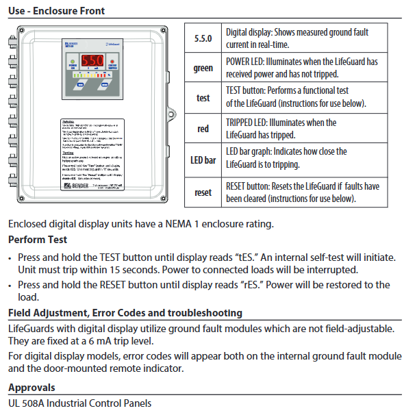
(2) Digital display operation (model ending with "- N-D")
Additional support for real-time display of ground fault current, LED bar chart indicating tripping risk;
Test: Press and hold the TEST button until the display screen shows "tES", and the device will trip within 15 seconds;
Reset: Press and hold the RESET button until the display screen shows "rES" to restore power supply;
Remote function:
Can connect to MK1500-D remote indicator, copy local testing/reset function;
Use AWG 18 shielded RS-485 cable connection and turn on the "R" switch on the grounding fault module;
MK1500-D requires an external power supply of 100-240VAC, 50/60Hz.
Safety and Compliance
Before installation, all power sources must be disconnected to avoid the risk of electric shock and arc flashover;
Separate isolation switches, branch protections, and/or overload relays need to be configured;
The three-phase three wire system can adopt direct grounding or resistance grounding methods;
Equipment troubleshooting and parameter adjustment should refer to the user manual of the protective relay.
Key issue
Question 1: LifeGuard ® What is the core protection function of the LG2 series? What are the differences in adaptation scenarios for different specifications?
Answer: The core protection function is to monitor the grounding fault current in the circuit in real time through current transformers. When the current reaches the tripping threshold, the load power supply is quickly cut off to prevent risks such as electric shock and equipment damage. The differences in adaptation scenarios for different specifications are as follows: ① Rated current<100A: Small size (305 × 254 × 152mm), suitable for small and medium power industrial equipment and branch circuit protection; ② Rated current 100A: larger size (406 × 356 × 203mm), suitable for high-power main circuits and heavy-duty equipment power protection; ③ Digital display version: Fixed 6mA trip level, real-time display of fault current, suitable for scenarios with requirements for protection accuracy; ④ Backplane only: needs to be installed inside the cabinet and is suitable for integrated industrial control systems.
Question 2: Install LifeGuard ® What are the key requirements for wiring and installation in the LG2 series? What compliance standards should be followed?
Answer: The key installation and wiring requirements are as follows: ① Wiring requirements: Use only copper wires, rated at 60 ℃ or above for<100A, and rated at 75 ℃ or above for 100A; All active conductors (including neutral wires) must pass through the current transformer, and the grounding wire must be directly connected to the grounding terminal, without passing through the transformer; ② Installation requirements: The shell should be wall mounted and fixed, with cable holes at the bottom and NEMA 4X connectors used; Only the backplane version needs to be installed inside the cabinet, with a vertical gap of 152mm for<100A and 203mm for 100A; ③ Compliance specifications: must be installed by licensed electricians, following local, state, and national electrical regulations, and complying with UL 508A industrial control panel standards; Separate isolation switches and overload protection devices need to be configured.
Question 3: LifeGuard ® What are the testing and reset operations for the LG2 series? What is the difference in operation between the digital display model and the regular model?
Answer: There are two ways to test and reset: ① Local operation: For ordinary models, the TEST (long press ≥ 2 seconds) and RESET (long press ≥ 1 second) buttons on the panel are used to achieve this; Long press TEST to display "tES" and RESET to display "rES" for digital models; ② Remote operation: Only the digital version supports connecting to the MK1500-D remote indicator, which can be achieved through its built-in button or external button. Operational differences: ① Testing process: Ordinary A/F grades require a 10 second self check, while D/E grades can be reset directly; The digital model has no self check waiting and must trip within 15 seconds; ② Function display: The digital version can view the grounding fault current in real time, and the LED bar chart indicates the risk of tripping. The ordinary version only indicates the status through a two-color LED; ③ Release level: The digital version is fixed at 6mA, while the regular version has four release levels: A/F/D/E. Please refer to the product configuration.
- OMRON
- ABB
- General Electric
- EMERSON
- Honeywell
- HIMA
- ALSTOM
- Rolls-Royce
- MOTOROLA
- Rockwell
- Siemens
- Woodward
- YOKOGAWA
- FOXBORO
- KOLLMORGEN
- MOOG
- KB
- YAMAHA
- BENDER
- TEKTRONIX
- Westinghouse
- AMAT
- AB
- XYCOM
- Yaskawa
- B&R
- Schneider
- KONGSBERG
- NI
- WATLOW
- ProSoft
- SEW
- ADVANCED
- Reliance
- TRICONEX
- METSO
- MAN
- Advantest
- STUDER
- DANAHER MOTION
- Bently
- Galil
- EATON
- MOLEX
- DEIF
- B&W
- ZYGO
- Aerotech
- DANFOSS
- Beijer
- Moxa
- Rexroth
- Johnson
- WAGO
- TOSHIBA
- BMCM
- SMC
- HITACHI
- HIRSCHMANN
- Application field
- XP POWER
- CTI
- TRICON
- STOBER
- Thinklogical
- Horner Automation
- Meggitt
- Fanuc
- Baldor
- SHINKAWA
- Other Brands
- UniOP
- KUKA
- Iba
- Beckhoff
-
 Basler DECS-200-2L Digital Excitation Control
 -
 Basler BE1-47N Voltage Phase Sequence Relay
 -
 Basler AEC63-7 Analog Excitation Controller 220-277V
 -
 Basler BE1-50/51B-107 Overcurrent Relay
 -
 Basler Electric BE1‑32R BE1‑E1P‑BON0F Protective Relay
 -
 Basler BE1-25 Solid State Time Overcurrent Relay M1EA6PA5S1F
 -
 Basler MVC 232 Manual Voltage Control Module 90 37000 103 60VAC 55VDC
 -
 Basler RAL6144-16GM Racer GigE Line Scan Camera
 -
 Basler SSR 63-12 Static Voltage Regulator
 -
 Basler BE1-51A Overcurrent Relay
 -
 Basler BE1-87T Solid State Protective Relay
 -
 Basler SR4A2B01B3A Static Voltage Regulator
 -
 Basler SSR 32-12 Static Voltage Regulator
 -
 Basler TRR00696 Transformer 1KVA 115V
 -
 Basler DECS-100-B15 AVR Replacement
 -
Basler BE1-27 Under-Voltage Relay
-
 Basler ACA2000-50GM Interface Module
 -
 Basler AEC63-7 Analog Excitation Controller
 -
 Basler PRS 250 Veri-Sync Relay
 -
 Basler SR4A-2B15B3A Static Voltage Regulator
 -
Basler BE1-32R Power Relay
-
Basler SR8A-2B06B3E Static Voltage Regulator
-
Basler BE1-81 O/U Frequency Relay
-
 Basler BE1-51A-K2E-W6M-B1N0F Overcurrent Relay
 -
Basler BE1-851 Overcurrent Relay G3A1S1 – 48-125V AC/DC
-
 Basler BEI-51 Overcurrent Relay – NSN 5945-01-293-2363
 -
Basler Electric L301KC Protective Relay – L301KC
-
 Basler DECS-100-B15 Automatic Voltage Regulator – Generator AVR
 -
 Basler SR4A-2B15B3A Static Voltage Regulator – SR4A2B15B3A
 -
 Basler UF 312 Under Frequency Protective Module – 9094700100
 -
Basler Electric MVC 232 Manual Control Module – 60VAC 55VDC 20A
-
Basler PRS 250 Veri-Sync Relay – Generator Synchronizing Relay
-
 Basler DECS-100-A05 Digital Regulator Review
 -
 Basler AEM-2020 Analog Expansion Module Specs
 -
 Basler DECS-100-B15 Digital Excitation Specs
 -
Basler Electric 9125600106 Regulator Component
-
Basler BE1-51A-K1E-W6M-B1N0F Overcurrent Relay
-
 Basler MVC-301 MVC 300 Excitation Controller
 -
 Basler SSR 32-12 Static Voltage Regulator
 -
 Basler 9-2849-00-101 Control Module
 -
Basler BE1-51A Overcurrent Relay
-
 Basler BE1-51/27R Overcurrent Relay
 -
 Basler BE1-51 Overcurrent Relay
 -
 Basler SR8A-2B15B3A Static Voltage Regulator
 -
 Basler BE32965001 Transformer and Timer Board
 -
 Basler 9174700100 EL200-7 Excitation Limiter
 -
 Basler BE2000E AVR Voltage Regulator
 -
Basler BE1-87G Differential Relay
-
 Basler BE21834001 Generator Control Module
 -
Basler DECS-100-B15 AVR
-
 Basler D90 96801 100 PCB Card
 -
 Basler XR2002F Voltage Regulator (110 VAC, 48-480 Hz)
 -
 Basler SR8A-2B14B3A Regulator
 -
 Basler 9561500100 Module
 -
 Basler DECS-400 BE1-11 System
 -
 Basler DECS-100-B15 Excitation Control
 -
 Basler SCP 210 Frequency Controller
 -
Basler SR4A-2B15B3A Static Voltage Regulator
-
Basler BE1-32R Power Relay
-
 Basler PIA2400-17GM Power Interface Adapter
 -
 Basler MVC 232 Manual Voltage Control Module
 -
 Basler SSR 32-12 Static Voltage Regulator
 -
Basler 5MW AVR Generator Voltage Regulator
-
 Basler VR63-4B Voltage Regulator
 -
Basler DECS-100-A05 AVR for Engine Generator
-
Basler DECS-100-B15 Automatic Voltage Regulator
-
Basler BE1-32R Directional Power Relay
-
Basler BE1-87B Differential Relay
-
 Basler UFOV 260A Protective Module
 -
 Basler 9-2614-02-100 PCB Rev M
 -
Basler DECS-100-B15 Digital AVR
-
 Basler 9284900103 PS DECS-400N
 -
 Basler D4N3H1U Intertie Protection
 -
 Basler DECS-100-B15 A15 AVR
 -
 Basler KR4F Voltage Regulator
 -
 Basler BE26434 T14 Transformer
 -
 Basler SR8A-2B15B3A Regulator
 -
 Westinghouse 774B472A12 AR Relay
 -
Basler DECS-100-B15 AVR
-
Basler XR2002F Regulator 110V
-
Basler SR125-E Static Regulator
-
Basler SSR 125-12 Regulator
-
Basler MOC2599 Motor Pot
-
 Basler BE1-DFPR Feeder Relay
 -
 Basler CBS 305 Current Boost
 -
Basler BE1-25 AutoSync
-
Basler MVC 300 Voltage Control
-
 Basler BE3-25A AutoSync
 -
 Basler KR7FF Static Regulator
 -
Basler 90-49000-100 Regulator
-
 Basler 880 kVA Dry Type Transformer Specs
 -
Basler Electric BE1-25 Sync-Check Relay Specs
-
 Basler SSR 125-12 Voltage Regulator Specs
 -
 Basler Electric BE1-851 Overcurrent Relay Review
 -
Basler Electric 149D930G02 Control Sub-Assembly
-
 Basler Electric BE1-81O/UT Frequency Relay Specs
 -
 Basler Electric BE1-51/27C Overcurrent Relay
 -
 Basler Electric 149D956G02 Industrial Component
 -
Basler Electric BE1-51A Overcurrent Relay Specs
-
 Basler Electric BE1-40Q Loss of Excitation Relay
 -
Basler DECS-200 Excitation Control System
-
 Basler DECS-200 Voltage Regulator 56-277V AC / 125V DC
 -
Basler BE1-87T Transformer Differential Relay
-
 Basler RDP-110-S1 Protection Relay
 -
 Basler BE1-700V Digital Protective Relay
 -
 Basler BE1-951 Overcurrent Protection System
 -
 Basler DECS-300 Digital Excitation Control
 -
 Basler DECS-200 Digital Excitation Control
 -
 Basler DECS-200-1C Excitation Control System
 -
Basler DECS-200-1L Digital Excitation Control
-
 Basler Electric BE1-GPS Generator Protection System
 -
Basler Electric DECS-200-1C Digital Excitation Controller
-
 Basler Electric DECS125-15 Excitation Control with Power Module
 -
Basler Electric BE1-87G Differential Relay
-
 Basler Electric BE1-11 Protection System I5A3M2P2N0EA00
 -
Basler Electric DECS-200-1C Excitation Control System
-
Basler Electric BE1-11g Generator Protection Relay
-
Basler Electric DECS 125-15-B2C1 V2.0.9 Excitation Control
-
Basler Electric BE1-81O/UT3ED1JA7N2F Frequency Relay
-
Basler Electric BE1-81O/UT3EE1YB7N1F Frequency Relay
-
 Basler Electric DECS-200-1L Digital Excitation Control System
 -
Basler DECS125-15-B2C1 Excitation Control
-
 Basler 9507900205 SSR Retrofit Voltage Regulator
 -
 Basler BE2000E Digital Voltage Regulator
 -
 Basler BE1-GPS Generator Protection System
 -
Basler DECS-250-CN1CN1N Digital Excitation Control
-
 Basler DGC-2020 Genset Controller
 -
Basler BE1-81O UT3ED1LA7N0F Frequency Relay (Variant)


