
YASKAWA U1000 series 24V power supply options (PS-U10L/PS-U10H)
YASKAWA U1000 series 24V power supply options (PS-U10L/PS-U10H)
Core Overview
This document is the installation manual for the Yaskawa U1000 series 24V power supply option (model PS-U10L/PS-U10H), which mainly introduces the functions, driver adaptation, installation process, operation verification, and safety specifications of the option. It provides users with full process guidance from receiving inspection to after-sales support, and is suitable for professional installation and maintenance personnel.
Core parameters and adaptation range of options
1. Option model and function definition
Model identification: This option includes two models - PS-U10L and PS-U10H, with the name "24V Power Supply" clearly indicating its core function: to provide a separate 24V DC power supply for the control circuit when there is no power supply for the main circuit of the drive, only supporting power supply for the control circuit, and unable to supply power to the main circuit of the drive 🔶 2-5 🔶 2-8 🔶 2-89.
Core purpose: With this option, users can access network communication, navigate digital operators, read I/O data, and view fault/parameter data while the main power is disconnected; If parameters need to be modified, the driver parameter o2-19 (UV state parameter writing selection) must be set to "1 (enabled)", otherwise the parameters cannot be modified even if the control circuit is powered on 🔶 2-91.
2. Adapt to the driver model and software version
According to document table 1 (Compatible Drive Models), the compatibility relationship between options and drives is as follows:
Option Model Adaptation Driver Series Driver Model Identification (Key Characters) Remarks
PS-U10L U1000, U1000L, Z1000U models containing "2" (such as CIMR-U 2 , CIMR-Z 2 ) require the driver software version to meet the standard
PS-U10H U1000, U1000L, Z1000U models containing "4" (such as CIMR-U , CIMR-Z 4 ) require the driver software version to meet the standard
The specific software version requirements are: U1000 series requires S5171, S1017 and above; U1000 crane specific models require S6412 and above; U1000L series requires S6213 and above. If the driver version is not met, it may cause the option to not work properly 🔶 2-96.
3. Key specifications and certification of options
On page 42 of the document (Table 4 Option Specifications), specify the technical parameters of the options and indicate the safety certification standards they comply with:
Electrical parameters: Input working voltage 24Vdc ± 20% (range 19.2V-28.8V), input current 1.9A, power consumption 38W, output holding time exceeding 50ms after power failure;
Environmental parameters: Operating temperature -10 ℃~+50 ℃ (14 ℉~122 ℉), short-term transportation and storage temperature -20 ℃~+60 ℃ (-4 ℉~140 ℃), weight 0.2kg (0.4lbs.), installation environment needs to match the specifications of the drive environment 🔶 2-431;
Certification standards: Compliant with UL (USA/Canada) and CE (Europe) certifications, with UL certification based on UL508C standard and CE certification in accordance with the Low Voltage Directive (2006/95/EC) and EMC Directive (2004/108/EC), following harmonized standards such as IEC/EN 61800-5-1 and EN 61800-3 🔶 2-431 🔶 2-499.

Detailed explanation of the entire installation process (including preparation, steps, and requirements)
1. Receipt inspection and installation preparation
(1) Receiving inspection items
After receiving the option, the user needs to complete three core checks: 1 Check if the appearance of the option is damaged during transportation. If damaged, immediately contact the transportation company (Yaskawa warranty does not include transportation damage); 2. Check if the option model is consistent with the order (refer to Figure 3 in the document for the location of the model identification); 3. Confirm that the packaging contents are complete, and the specific list is as follows 🔶 2-103 🔶 2-104 🔶 2-105,:
Item name, quantity, and purpose
Signal/power transmission between one option connecting cable and the driver
M3 screws with 3 options for fixation (some installation methods require the use of screws)
The installation method of the six parts of the stud (such as C, D, E, F) includes option fixing
6 zip ties for organizing cables to avoid clutter or pressure
Installation Manual (TOBPC73060095. pdf) 2 copies of technical guidance (including both Chinese and English versions)
Option body (PS-U10L/PS-U10H) 1 core functional component
If you receive an incorrect model or option that does not work properly, you need to contact the supplier for assistance.
(2) Essential Tool List
The document clearly lists the required tools and specifications for installation. Missing or using non compliant tools may result in installation failures:
Cross screwdriver: M4 metric specification, or # 1, # 2 American standard specification, used for disassembling/installing drive cover screws;
One letter screwdriver: blade thickness 0.4mm, blade width 2.5mm, used for wiring operation of option terminal block TB1;
Wire stripping pliers: used to strip the insulation layer of cables to ensure good contact between the wiring terminals;
Wrench: Open end wrench, ring wrench or ratchet wrench (diameter 6mm), used to tighten bolts, the tightening torque should be controlled at 0.5-0.7N · m 🔶 2-109;
Attention: The document does not include cable pre-processing tools (such as crimping pliers), and users need to prepare them themselves.
2. Classification of installation methods and operating steps
The document categorizes installation methods into six types, A-F, based on the differences in drive models. The core differences lie in the option fixing method (only screws/screws+studs), cable connection interface (CN1 direct connection/CN19 adapter), and installation position. The following are the key information and general steps for each type of method:
(1) Installation method classification and driver adaptation
Installation method: Adapt to driver model (example) Fixed method: Cable connection interface corresponds to document page number
A U1000 2 0028-2 0081, 4 0011-4 0077; U1000L 20028-20068; Z1000U 2 0028-2 0081 M3 screw option only, CN1 direct connection to driver reserved interface 22
B U1000 2 0104, 2 0130, 4 0096, 4 0124; U1000L 2 0081, 2 0104; Z1000U 2 0104, 2 0130 only M3 screw option CN1 direct connection to driver reserved interface 25
C U1000 2 0154, 2 0192, 4 0156, 4 0180; Z1000U 2 0154, 2 0192 screw+stud option CN1 connected to driver CN19 28 via cable A
D U1000 2 0248, 4 0216, 4 0240; Z1000U 2 0248, 4 0216 screw+stud options CN1 connected to driver CN19 31 via cable B
E U1000 40302-40414; Z1000U 4 0302-4 0414 screw+stud option CN1 connected to driver CN19 34 via cable C
F U1000 4A0477-4A0930; Z1000U 4A0477-4A0930 screw+stud option CN1 connected to driver CN19 37 via cable B
(2) General installation steps (taking method A as an example, differences in other methods have been marked)
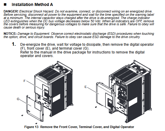
Power off and discharge: Disconnect all power sources from the drive, wait for the internal capacitor to discharge (at least 5 minutes until the CHARGE indicator light on the drive goes out), confirm that there is no dangerous voltage, and then remove the digital operator (F), front cover (E), and terminal cover (G). The removal steps should refer to the manual provided with the drive;
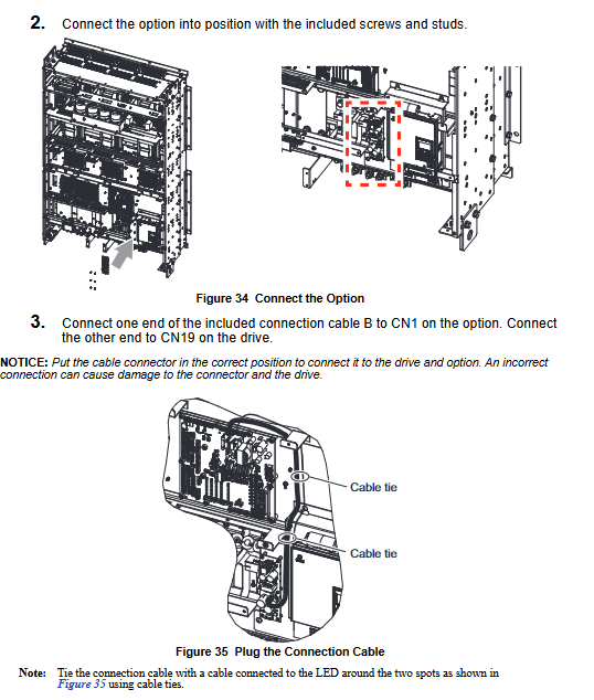
Option fixing: Use the M3 screw inside the package to fix the option in the designated position of the driver (refer to Figure 4 in the document for the position), ensuring that it is firmly fixed and not loose;
Cable connection: Pull out the loose end of the reserved connection cable for the driver, insert it into the CN1 interface of the option, pay attention to the interface direction, and reverse insertion may damage the connector or driver;
Cover plate reset: Reinstall the driver front cover, terminal cover, and digital operator to ensure that the cables are not squeezed by the cover plate and to avoid insulation layer damage causing short circuits;
External power supply wiring: Go to the "Wire the Option" section on page 40 of the document and connect an external 24V power supply to the option terminal block TB1 (terminal definition: 24=+24VDC input, 0=0V, FE=ground). The wiring steps are as follows:
Loosen the TB1 terminal screw with a straight screwdriver;
Peel off the insulation layer of the cable (with a bare length of about 5.5mm, to avoid the wire ends from unraveling);
Insert the cable into the corresponding terminal and tighten the screw (torque 0.22-0.25N · m);
Wrap the cable shielding layer with heat shrink tubing or electrical tape to avoid short circuits caused by contact with other circuits 🔶 2-393;
(3) Special installation requirements (for C-F method)
Fixed difference: The C-F method requires the installation of screws (tighten with a 6mm wrench, torque 0.5-0.7N · m) first, and then fix the option with screws;
Cable differences: C method uses connection cable A, D/F method uses connection cable B, E method uses connection cable C, and the cables need to be sorted according to the document diagram (such as Figure 23, 27) and fixed with zip ties to avoid cable entanglement or compression.
3. Key wiring specifications
Power requirements: The external 24V power supply must be UL Listed Class 2 certified (or equivalent) to avoid the risk of electric shock or fire caused by the use of non certified power supplies. The power supply must be able to provide at least 3A current (the instantaneous current when the option is powered on is twice the conventional value, lasting for about 0.5 seconds);
Cable specifications: Shielded twisted pair cables are required for control cables, with a recommended wire diameter of 0.75mm ² (18AWG). The suitable wire diameter range for single strand cables is 0.25-1.5mm ² (24-16AWG), and the suitable wire diameter for crimping terminals is 0.25-0.5mm ² (24-20AWG);
Shielding treatment: The cable shielding layer needs to be grounded at one end (connected to the driver grounding terminal) to avoid circulating current caused by double ended grounding, and the grounding area should be as large as possible (refer to Figure 40 in the document);
Operation verification and troubleshooting
1. Run verification steps
After installation and wiring are completed, the following steps should be taken to verify whether the option functions properly:
Power on the main circuit of the driver and confirm that the external 24V power supply has been connected to the TB1 terminal of the option, and that the option is properly connected to the driver cable;
Disconnect the power supply of the main circuit of the drive, and the option should supply power to the control circuit of the drive;
Observe the red LED indicator light on the option. If it lights up, it indicates that the option is working properly;
When checking the digital operator of the drive, it should briefly display "Fdv" or "AUv" (undervoltage prompt) for about 10 seconds. This prompt is a normal phenomenon, indicating that the control circuit has been powered through the option 🔶 2-413;
2. Handling of abnormal situations
If the option LED does not light up: check if the external 24V power supply is normal (voltage range 19.2-28.8V), if the TB1 terminal wiring is loose or reversed, and if the option is in good contact with the driver cable;
If there is no "Fdv/AUv" prompt on the operator: first confirm that the wiring is correct, then check if the driver parameter o2-19 is set correctly. If it is still abnormal, it may be a problem with the option or driver, and contact Yaskawa after-sales service;
In addition, Table 3 (Power Supply and Control Circuit) of the document specifies the operation of the control circuit and driver under different power states, which can be used to assist in fault diagnosis:
Driver main circuit power options, power supply status, driver control circuit operation status, driver operation possibility
ON, ON, can run normally
ON/OFF can run
OFF/ON can access data (parameters/faults) but cannot run
OFF: Stop running and cannot run
Core Security Standards
(1) Electrical safety
Prohibited live operation: During installation, wiring, and maintenance, all power sources must be disconnected and the capacitor must be discharged (at least 5 minutes). The CHARGE light must be turned off before operation, otherwise it may cause electric shock death or serious injury 🔶 2-133;
Authorization operation requirements: Only authorized personnel who have received training are allowed to install and maintain. Unauthorized personnel operation may cause safety accidents;
Prohibited from modifying equipment: It is not allowed to modify the driver body or option circuit without authorization. Modifying will result in the expiration of the warranty, and Yaskawa will not be responsible for any damage caused by this;
(2) Fire prevention and equipment protection
Terminal torque requirements: All terminal screws must be tightened to the specified torque (such as TB1 terminal 0.22-0.25N · m, screw 0.5-0.7N · m). Too loose may cause poor contact, heat generation, and fire, while too tight may damage the terminals 🔶 2-149;
Static electricity protection: When in contact with options, drivers, or circuit boards, it is necessary to follow the ESD (electrostatic discharge) protection process (such as wearing an anti-static wristband) to avoid static electricity damaging the circuit;
Environmental restrictions: It is prohibited to expose options or drivers to halogen disinfectants, and they should not be stored in fumigated wooden packaging to avoid chemical damage to electrical components
- ABB
- General Electric
- EMERSON
- Honeywell
- HIMA
- ALSTOM
- Rolls-Royce
- MOTOROLA
- Rockwell
- Siemens
- Woodward
- YOKOGAWA
- FOXBORO
- KOLLMORGEN
- MOOG
- KB
- YAMAHA
- BENDER
- TEKTRONIX
- Westinghouse
- AMAT
- AB
- XYCOM
- Yaskawa
- B&R
- Schneider
- KONGSBERG
- NI
- WATLOW
- ProSoft
- SEW
- ADVANCED
- Reliance
- TRICONEX
- METSO
- MAN
- Advantest
- STUDER
- DANAHER MOTION
- Bently
- Galil
- EATON
- MOLEX
- DEIF
- B&W
- ZYGO
- Aerotech
- DANFOSS
- Beijer
- Moxa
- Rexroth
- Johnson
- WAGO
- TOSHIBA
- BMCM
- SMC
- HITACHI
- HIRSCHMANN
- Application field
- XP POWER
- CTI
- TRICON
- STOBER
- Thinklogical
- Horner Automation
- Meggitt
- Fanuc
- Baldor
- SHINKAWA
- Other Brands
- UniOP
- KUKA
- Iba
-
 GE AT868 AquaTrans Ultrasonic Flow Transmitter
 -
 ABB PFSA107-Z42 DTU Stressometer Digital Transmission Unit
 -
 ABB PFSA240 3BSE073476R1 Roll DC Supply Unit
 -
 Fanuc A16B-2201-0320 CPU MAIN Board
 -
 Pilz 475650 PNOZ 1 Safety Gate Relay
 -
 Omron NSH5-AL001 HMI Interface Unit
 -
 Allen-Bradley 1756-OF8 Analog Output Module
 -
 Siemens 6SL3210-1SE31-0AA0 Power Module 45kW
 -
 PMA TB45-110-00000-000 Temperature Limiter
 -
 PSR-SCP-24DC-ESD-5x1-1x2-300 Safety Relay
 -
 Pilz 774140 PZE 9 Safety Relay
 -
 Telemecanique TSXRKN82F PLC Rack Chassis
 -
 Mitsubishi R16CPU PLC CPU Module
 -
 OMRON C500-PS223-E Power Supply Module
 -
 Siemens 3VL4731-1DC36-0AA0 Circuit Breaker
 -
 Siemens 7ML5201-0EA0 Ultrasonic Level Transmitter
 -
 OMRON NQ3 NQ5 Touch Panel HMI
 -
 OMRON CJ1W-AD081-V1 Analog Input Module
 -
 OMRON NJ301-1100 Machine Automation Controller
 -
 B&R X20BC00G3 EtherCAT Bus Controller
 -
 Schneider ATV212HD22N4S Variable Speed Drive
 -
 B&R 8B0C0320HW00.002-1 Power Supply Module
 -
 Mitsubishi OSA105S2A Incremental Rotary Encoder
 -
 Pilz 777514 PNOZ XV3P Safety Relay
 -
 Gould AS-884A-111 Modicon 884 Controller
 -
 Siemens 6SC6130-0FE00 SIMODRIVE Control Card
 -
 Omron CV500-PS221 PLC Power Supply Module
 -
 ABB CM577-ETH AC500 PLC Ethernet Module
 -
 Omron NX-SIH400 Safety Input Unit NX Series
 -
 Omron NJ501-1300 Machine Automation Controller
 -
 Siemens 3VT8563-2AA03-2KA2 Molded Case Breaker
 -
 Pilz PNOZ m1p ETH 773103 Safety Controller
 -
 Omron CJ1H-CPU66H-R CJ1 Series CPU Module
 -
 ASI ASI533-S00 PLC Module S1
 -
 Mitsubishi AJ71C21-S1 Serial Module
 -
 Keyence IX-1000 Laser Sensor Amplifier
 -
 Siemens 6SN1145-1AA01-0AA1 Power Module
 -
 Siemens 3VA2340-5HL32-0AA0 MCCB 400A
 -
 Mitsubishi OSA104S Absolute Encoder
 -
 Siemens 6ES7350-1AH03-0AE0 FM 350-1 Counter
 -
 Siemens 6SE7038-6EK84-1JC2 IGD8 Gate Driver
 -
 Eaton EASY819-AC-RC Programmable Relay
 -
 Omron CPM1A-40CDT-D PLC 24V DC
 -
 Omron NA5-12W101B-V1 12-inch Programmable Terminal
 -
 Siemens 6ES7331-7KF02-0AB0 Analog Input SM 331
 -
 Moxa PTC-101-S-SC-HV Photoelectric Converter
 -
 Fanuc A20B-3300-0031 CNC Control Circuit Board
 -
 OMRON NA5-7W001B-V1 Programmable Terminal HMI
 -
 Parker AH385851U002 590C DC Drive Power Board
 -
 ABB 3BSE040662R1 AI830A Analog Input Module
 -
 DOLD BF9250.01/001 Solid State Relay
 -
 Siemens 6ES7331-7KF02-0AB0 SIMATIC S7-300 SM 331
 -
 ABB 07AC91 I6 GJR5252300R3101 Advant Controller 31
 -
 Schneider HMIST6500 Touch Screen HMI
 -
 Phoenix IL PN BK DI8 DO4 2TX-PAC Bus Coupler
 -
 NLTECH NL8060AC21-21D 8.4 inch LCD Display
 -
 Mitsubishi A2NCPU-P21 CPU Module A2NCPUP21
 -
 1841-PL1-B-LH-ES Pressure Controller
 -
 Mitsubishi GT2512-STBA GT2512-STBD HMI
 -
 Cosel PJA600F-24 24V 600W Power Supply
 -
 B&R X67DM1321 Digital Mixed Module
 -
 Fanuc A16B-1310-0010 Power Supply Unit
 -
 Festo VABF-S4-1-V2B1-C-VH-20 Vacuum Generator
 -
 Mitsubishi A3ACPUP21 A3ACPU-P21 CPU
 -
 Mitsubishi Mazak PD14B-1 Power Supply
 -
 Siemens 6SY7000-0AC80 Module
 -
 PILZ 774400 PDZ Safety Relay
 -
 Mitsubishi A1SX81 Digital Input Module
 -
 Asyst Gasonics R94-1163 Controller 112671
 -
 Cincinnati Milacron 3 545 1000A Card
 -
 Siemens 6DD1607-0AA2 UPS Module
 -
 Square D 8536SCG3V02S Motor Starter
 -
 Siemens 6SL3100-1DE22-0AA1 Control Supply
 -
 Beckhoff EL9400 EtherCAT Power Terminal
 -
 Fanuc A16B-2202-0421 Power Supply Board
 -
 Turck TBEN-LG-8DIP-8DOP I/O Block
 -
 Euchner MGB-L1B-PNA-L-121861 Safety Switch
 -
 Pilz 772170 PNOZ M EF 1MM Safety Expansion
 -
 Mitsubishi AY51 MELSEC-A Output Module
 -
 Advantech AMAX-5056-A 8-Channel Digital Output
 -
 NXP MC912D60ACPV8 16-Bit MCU 60KB Flash
 -
 Omron C500-PS223-E SYSMAC PLC Power Supply Unit
 -
 Balluff BNI0047 BNI PBS-302-101-Z001 Profibus Module
 -
 Siemens 6SN1118-0DM31-0AA0 Regulation Card
 -
 Bently Nevada 9200-02-01-10-00 Sensor
 -
 Omron C500-PS223-E Power Supply Unit
 -
 Cognex COG-VC5-120-000 Vision Controller
 -
 ABB P-HC-BRC-40000000 Bridge Controller
 -
 Mitsubishi AJ71E71N-B5T PLC Module
 -
 Phoenix PSI-REP-PROFIBUS/12MB 2708863
 -
 Siemens 6SL3210-5BE31-8UV0 Converter
 -
 ABB CI868K01-eA 3BSE048845R2 Module
 -
 Honeywell S7999D1006 Touch Screen
 -
 Keyence CA-CHX10U Repeater Unit
 -
 Keyence VT5-W07 Touch Screen HMI
 -
 Keyence KV-8000 PLC CPU
 -
 Siemens 7MH4900-3AA01 Weighing Module
 -
 Omron C200HS-CPU01-E Programmable Controller
 -
 CD22-35AM12 Inductive Sensor
 -
 Mitsubishi A2NCPUR21-S1 PLC CPU
 -
 Siemens 6ES7331-7FK02-0AB0 Analog Input
 -
 Schneider HMIST6500 Touch Screen HMI
 -
 0970 PSL109 Module Industrial Control
 -
 Schneider LC1F500P7 Contactor 500A
 -
 Mitsubishi GT2512-STBA GT2512-STBD HMI
 -
 Omron NJ1019000 Machine Automation Controller
 -
 Siemens 6SN1112-1AC01-0AA1 Power Module
 -
 Eaton AE16KNS0AB Bimetallic Overload Relay
 -
 ABB 3bse036456r1 Ai825 Analog Input 4 Ch
 -
 Fuji Electric 7MBR50SB120-50 IGBT Module
 -
 Schneider XPSMC32ZP Safety Relay
 -
 Siemens 3VL4740-2AA36-0AA0 Circuit Breaker
 -
 ABB PharpSFan03000 Mpsiii Fan System Monitor
 -
 Honeywell DPCB21010002 IRTP131 PCB
 -
 Siemens 6ES7214-1HG40-0XB0 CPU 1214C
 -
 Siemens 6ES7350-1AH03-0AE0 FM 350-1
 -
 PILZ PNOZ mm0.1p 772001 Safety Relay
 -
 E2V EVX12DS130AGC 12DS130 Module
 -
 Siemens 3RT5066-6AB36 Contactor
 -
 HIRSCHMANN RS20-0800T1T1SDAEHC09.1.00 Switch
 -
 Q4XTILAF500-Q8 Laser Range Sensor
 -
 OMRON CVM1-BC103 Base Unit 145752
 -
 CAREL RITC400001 Card
 -
 Eaton LZMN3-AE400 Molded Case Circuit Breaker
 -
 Fanuc A20B-3300-0031 Control Circuit Board
 -
 Siemens 6ES7450-1AP01-0AE0 S7-400 FM 450-1
 -
 Fanuc A90L-0001-0317/F Spindle Fan Motor
 -
 Schneider TM262L10MESE8T Logic Controller


