
WESTINGHOUSE MAX-VH ™/ MAX-VHP ™ Series vertical hollow shaft induction motor
WESTINGHOUSE MAX-VH ™/ MAX-VHP ™ Series vertical hollow shaft induction motor
Brand positioning and core product values
TECO Westinghouse, as a globally renowned electrical brand with a century of technological accumulation, has launched the MAX-VH ™/ MAX-VHP ™ The series of vertical hollow shaft squirrel cage induction motors are specially designed for industrial heavy-duty scenarios, with a core positioning of "high reliability, strong load adaptation, and high-efficiency energy-saving" power solutions. The product covers a power range of 7.5-1000 HP, suitable for low voltage (230V/460V) and medium voltage (2300V/4000V) power supply, with synchronous speeds covering 900/1200/1800 RPM. It is widely used in industrial equipment such as pumps and compressors that require direct coupling transmission. Its core value lies in stable operation in environments ranging from -15 ° C to 40 ° C, high humidity, and even hazardous environments (Class 1, Div 2) through "high rigidity structural design, F-class insulation system, and multi protection level adaptation". At the same time, with excellent performance such as a 1.15 service factor and 125% overspeed tolerance, it ensures industrial production continuity. Coupled with a 36 month warranty, it provides users with long-term and worry free power support.
Overview of Product Core Technical Parameters
(1) Basic specifications and certification standards
Category specific specifications
Product series MAX-VH ™ (Standard efficiency) MAX-VHP ™ (NEMA High Efficiency Level)
Motor type: squirrel cage induction motor (SCIM)
Power range: Low voltage: 7.5-800 HP; Medium voltage: 200-1000 HP
Voltage adaptation for low voltage: 230V/460V (compatible with 208V), only 460V for 150 HP and above;
Medium voltage: 2300V/4000V
Frequency adaptation 60 Hz (compatible with 50 Hz for low-voltage models)
Synchronous speeds of 900 RPM, 1200 RPM, 1800 RPM
Service coefficient of 1.15 (sine wave power supply, continuous operation); 1.0 (PWM power supply)
Weather Protected Type 1: IP23;
TEFC type (Completely Enclosed Fan Cooled): IP55
Certification standard design standards: NEMA MG-1, MG-13;
Test standard: IEEE-112 (Method B/F);
Hazardous environment certification: CSA Class 1, Div 2, Group B, C, D (Temp T3)
Warranty period of 36 months (from production date)
(2) Structure and material parameters
Category specific specifications
Core structure rack/flange bracket/upper bracket: high-grade cast iron;
Shaft system: 1045 carbon steel hollow shaft (high strength, high wear resistance);
Core: C5 grade cold-rolled insulated electromagnetic steel plate;
External components: aluminum alloy external fan, steel plate vertical splash cover
Winding and insulated stator winding: Low voltage is high pulse withstand polyester enameled copper wire+mica insulation, medium voltage (449TP and above) is mica+glass insulation formed coil;
Insulation level: F-class insulation system (Class B temperature rise);
Immersion treatment: Low pressure phenolic alkyd resin paint (2 immersion baking+1 spraying), medium pressure VPI epoxy paint
Rotor structure 449TP and below: aluminum conductor squirrel cage type (end ring and fan blade integrated casting);
5000 frames and above: copper or copper alloy bar squirrel cage type
Surface treatment: Phenolic anti rust primer+clear coat surface coating, standard color: RAL 7032 textured powder coating
Installation method: flange installation (IM3011), matched with P-Base base (compliant with NEMA MG1-18-238 standard)
(3) Key performance parameters
Category specific specifications
Temperature rise resistance method measurement: ≤ 105 ℃ at S.F.1.15; S. F.1.0 ≤ 80 ℃
Tolerance for overspeed: 125% synchronous speed (lasting for 2 minutes);
Overturn: 160% rated torque (lasting for 15 seconds);
Variable frequency adaptation: 10:1 variable torque (inverter operating condition)
Low voltage startup methods: direct startup, star delta startup, partial winding startup, VFD startup;
Medium voltage: direct start, VFD start
Low voltage models with power factor (FL PF): 81.0% -90.7%; Medium voltage models: 75.6% -87.3%
Full load efficiency (FL EFF) MAX-VH ™: 88.5%-95.4%; MAX-VHP ™: 91.0% -96.2% (NEMA High Efficiency)
Downward thrust 2600 LBS-33800 LBS (graded by power and frame number)
Product System and Core Series Detailed Explanation
(1) Low voltage series (230V/460V)
1. MAX-VH ™ Standard Efficiency Series (VH Model)
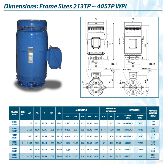
Power coverage: 7.5-400 HP (1800 RPM), frame number 213TP-449TP.
Example of core parameters:
VH0754FP (75 HP): Full load efficiency 94.1%, power factor 84.5%, 460V full load current 88.5A, downward thrust 6000 LBS, transport weight 989 LBS.
VH4004FP (400 HP): Full load efficiency 95.4%, power factor 88.5%, 460V full load current 444A, downward thrust 13200 LBS, transport weight 3818 LBS.
Applicable scenarios: General industrial scenarios with moderate energy efficiency requirements, such as ordinary water pumps and fan drives.
2. MAX-VHP ™ Efficient series (VHP/VHTP models)
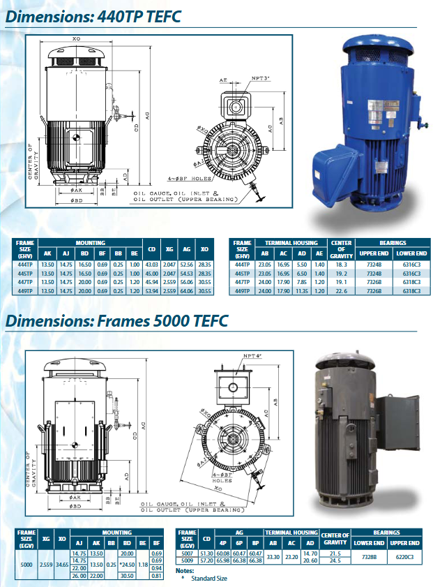
Power coverage: 7.5-800 HP (1800 RPM), frame number 213TP-5810P, including customized fire pump models (compliant with ANSI/UL 1004-5).
Example of core parameters:
VHP1504 (150 HP): Full load efficiency 95.8%, power factor 86.0%, 460V full load current 171A, downward thrust 10700 LBS, transport weight 1815 LBS.
VHTP8004 (800 HP): TEFC protection, full load efficiency of 96.2%, power factor of 86.0%, 460V full load current of 904A, downward thrust of 10100 LBS, transport weight of 9220 LBS.
Core advantages: NEMA high-efficiency certification, lower energy consumption, suitable for industrial scenarios with strict energy efficiency requirements (such as data centers and high-end manufacturing).
(2) Medium voltage series (2300V/4000V)
1. VHKP high thrust series
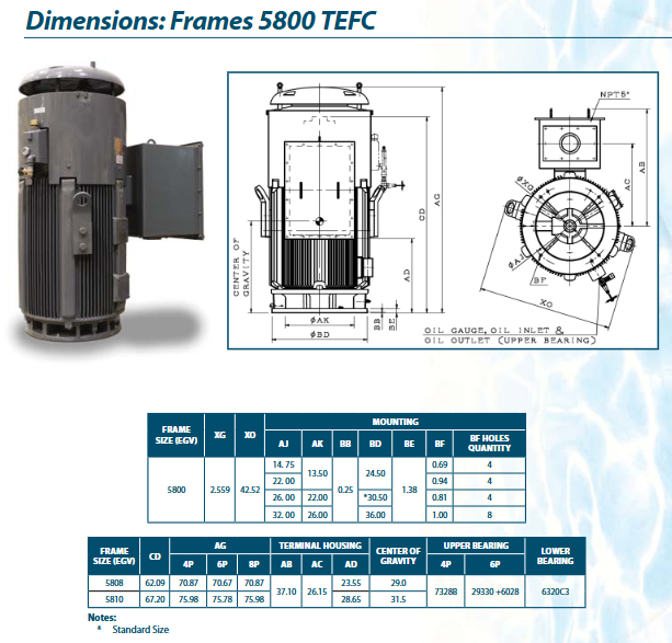
Power coverage: 200-1000 HP, speed 1200/1800 RPM, frame number 449TP-5810P.
Example of core parameters:
VHKP5004 (500 HP, 1800 RPM): Full load efficiency of 95.0%, power factor of 87.6%, downward thrust of 30900 LBS, transport weight of 3980 LBS.
VHKP10004 (1000 HP, 1800 RPM): Full load efficiency of 95.0%, power factor of 87.3%, downward thrust of 30100 LBS, transport weight of 6510 LBS.
Applicable scenarios: heavy-duty equipment such as large industrial pumps and compressors that require high thrust and high voltage power supply.
2. VHKTP TEFC high thrust series
Power coverage: 200-700 HP, speed 1200/1800 RPM, frame number 449TP-5810P.
Core features: IP55 protection, suitable for harsh environments, with a maximum downward thrust of 22300 LBS, designed specifically for medium voltage heavy loads and high protection requirements.
Core structure and key component design
(1) Bearing and lubrication system
1. Bearing configuration (graded by frame number)
Frame number range thrust bearing (upper) guide bearing (lower)
213TP-286TP grease refillable angular contact bearing, filled with Polyrex EM grease pre filled grease double shielded rolling bearing
324TP-5810P oil lubricated angular contact/spherical bearing with oil level sight glass (maximum 300% thrust adaptation) bracket installation vacuum degassing open bearing, with grease release valve
2. Requirements for lubricating media
Guide bearing: Lithium based mineral grease (Multemp SRL) or Polyrex EM grease.
Thrust bearing (324TP-449TP): Turbine oil, viscosity 300 S.S.U. @ 100 ° F.
Lubrication key: Oil lubricated models need to regularly check the oil level, while grease lubricated models need to regularly replenish grease according to operating conditions to avoid dry friction damage.
(2) Electrical system design
1. Wiring and terminals
Lead terminal: 210TP-405TP has 12 leads (230V supports partial winding start, 230V/460V supports star delta start); 444TP and above are 6-lead wires (460V supports partial winding startup).
Junction box: made of cast iron material, can rotate 90 °, with threaded interface, convenient for external conduit access, built-in grounding terminal (including P-Base grounding terminal).
2. Protection and safety
Winding protection: F-class insulation system, excellent temperature resistance, suitable for frequency converter pulse impact.
Hazardous environment adaptation: TEFC models have passed CSA certification and can be used in Class 1, Div 2, Group B, C, D scenarios, with a minimum temperature level of T3.
(3) Highlights of Mechanical Structure
1. High rigidity frame
Adopting high-grade cast iron integrated casting, the upper bracket with frame number 449TP-5810P is designed with an integrated oil tank, balancing structural strength and lubrication storage requirements.
The flange bracket size complies with NEMA MG1-18-238 standard, ensuring installation compatibility and transmission stability.
2. Hollow shaft design
1045 carbon steel material, hollow structure reduces weight while ensuring strength, suitable for direct coupling transmission, shaft diameter size graded according to frame number (BX size 1.001-2.501 inches), strict tolerance control (≤ 1.5 inches:+0.001/-0.000 inches; > 1.5 inches:+0.0015/-0.000 inches).
3. Auxiliary components
Standard configuration: wedge key, non reversing pawl (NRR, ball type spark free design), heavy-duty beryllium copper ball to prevent equipment from rotating in the opposite direction and causing damage.
Optional configurations: stable liner, alternative coupler, customized P-Base size.
Installation and operation specifications
(1) Installation requirements
1. Environmental conditions
Temperature: -15 ℃~40 ℃ (WP1 type), TEFC model is suitable for hazardous environments (Class 1, Div 2).
Humidity: ≤ 80% RH (no condensation).
Altitude: ≤ 3300 feet (approximately 1006 meters).
Installation method: Flange installation (IM3011), the P-Base base needs to be matched with the corresponding model according to the frame number (such as 210TP with 31103F412X1C0), and it needs to be machined by the factory before installation.
2. Coupling and fixation
Coupling kit: Each motor comes standard with one set of couplers, and the BX size is adapted according to the frame number (such as 213TP standard BX=1.001 inches). Separate procurement requires pricing according to the list.
Fixed requirement: The anchor bolts should be tightened according to ISO metric thread to ensure no vibration displacement during the transmission process.
(2) Operating standards for operation
1. Check before startup
Electrical inspection: power supply voltage fluctuation ≤ ± 10%, frequency fluctuation ≤ ± 5%, three-phase voltage balance; The insulation resistance meets the standard (F-class insulation ≥ 100 M Ω @ 40 ℃).
Mechanical inspection: The oil level of the oil lubricated model is within the normal range of the sight glass, and there is no grease leakage in the grease lubricated model; The bearing is not stuck, and the hollow shaft rotates smoothly; The function of the non reversing pawl is normal.
Protection inspection: WP1 type protective net is undamaged, TEFC model is well sealed, and there is no foreign object intrusion.
2. Operation monitoring
Key parameters: Full load current not exceeding rated value, three-phase current imbalance ≤ ± 5%; Bearing temperature ≤ 95 ℃, winding temperature ≤ 105 ℃ (S.F.1.15).
Exception handling: If overspeed or over torque conditions occur, it is necessary to ensure that the duration does not exceed the specified limit; When abnormal noise or increased vibration occurs, immediately stop the machine to investigate bearing or coupling issues.
3. Shutdown specifications
Normal shutdown: First reduce the load, then cut off the power. TEFC models need to wait for the fan to completely stop before shutting down the cooling system.
Long term shutdown: Rotate the hollow shaft regularly (at least 1 turn per month) to avoid bearing corrosion; Oil lubricated models require draining the oil tank, while grease lubricated models require replenishing new grease.
Maintenance and upkeep system
(1) Maintenance cycle and core projects
Key operational points for core projects in the maintenance cycle
Daily visual inspection and oil level monitoring check that the motor surface is free of damage, grease and oil leakage; The oil level of the lubrication model is at the center position of the sight glass
Weekly current/temperature monitoring+abnormal noise investigation records three-phase current and bearing temperature; Listen to the sound of the motor running, no abnormal vibration or friction sound
Monthly bearing maintenance+junction box inspection, grease lubrication for machine models (quantified by bearing model); The terminal of the junction box is not loose or oxidized
Measure the insulation resistance of the winding with a 500VDC megohmmeter every quarter to ensure it is ≥ 100 M Ω at 40 ℃
Annual comprehensive disassembly inspection and cleaning of winding dust; Check the wear of the bearings and replace them if necessary; Check for no reverse pawl function
Deeply maintain and replace bearings and lubricating media every 3 years; Check the connection between the rotor guide bar and the end ring; Re tighten all bolts
(2) Key component maintenance details
1. Bearing maintenance
Lubricating with grease: Add grease according to the bearing model (such as 6312C3, add 40g of grease), and run without load for 10-30 minutes after adding grease to discharge the old grease.
Oil lubrication: Replace the turbine oil once a year, rinse the oil tank with a cleaning agent before replacement to ensure that there are no impurities left; Timely replenish when the oil level is below the minimum mark to avoid dry friction.
2. Winding maintenance
Cleaning: Use compressed air (pressure ≤ 4 kg/cm ²) to blow away dust on the surface of the winding, wipe off oil stains with neutral cleaner, and prohibit the use of chlorine containing solvents.
Moisture prevention: When the machine is shut down for a long time, use the space heater to maintain the winding temperature 3 ℃ higher than the dew point to prevent condensation from damaging the insulation.
3. Maintenance of Non Reversing Claw (NRR)
Regularly check the engagement between the pawl and ratchet, ensuring no jamming or wear; Replace the pawl ball bearings every 3 years to avoid reverse rotation failure.
Selection Guide and Application Scenarios
(1) Selection core logic
Power matching: Select the motor power based on 1.2 times the rated load power, ensuring redundancy (such as selecting a 60 HP motor for a 50 HP load).
Voltage adaptation: Choose 230V/460V for low voltage scenarios (≤ 400 HP) and 2300V/4000V for medium voltage scenarios (≥ 200 HP).
Protection level: Choose WP1 (IP23) for ordinary industrial environments, and TEFC (IP55) for humid/dusty/hazardous environments.
Energy efficiency requirement: MAX-VH is selected for general scenarios ™, Choose MAX-VHP for energy-saving scenarios (such as continuous operation equipment) ™ (NEMA high efficiency level).
Thrust adaptation: Select the corresponding frame number for downward thrust according to the load (e.g. 444TP frame for 10000 LBS thrust).
(2) Typical application scenarios
Industrial pumps: fire pumps, sewage pumps, chemical centrifugal pumps (especially large pump sets that require high thrust and direct coupling).
Compressors: air compressors, refrigeration compressors, suitable for continuous operation conditions.
General machinery: fans, transmission gearboxes, suitable for scenarios with high requirements for speed stability.
Special environments: hazardous environments such as petrochemicals and mines (TEFC models), high temperature/high humidity industrial workshops (WP1 models).
- OMRON
- ABB
- General Electric
- EMERSON
- Honeywell
- HIMA
- ALSTOM
- Rolls-Royce
- MOTOROLA
- Rockwell
- Siemens
- Woodward
- YOKOGAWA
- FOXBORO
- KOLLMORGEN
- MOOG
- KB
- YAMAHA
- BENDER
- TEKTRONIX
- Westinghouse
- AMAT
- AB
- XYCOM
- Yaskawa
- B&R
- Schneider
- KONGSBERG
- NI
- WATLOW
- ProSoft
- SEW
- ADVANCED
- Reliance
- TRICONEX
- METSO
- MAN
- Advantest
- STUDER
- DANAHER MOTION
- Bently
- Galil
- EATON
- MOLEX
- DEIF
- B&W
- ZYGO
- Aerotech
- DANFOSS
- Beijer
- Moxa
- Rexroth
- Johnson
- WAGO
- TOSHIBA
- BMCM
- SMC
- HITACHI
- HIRSCHMANN
- Application field
- XP POWER
- CTI
- TRICON
- STOBER
- Thinklogical
- Horner Automation
- Meggitt
- Fanuc
- Baldor
- SHINKAWA
- Other Brands
- UniOP
- KUKA
- Iba
- Beckhoff
-
 Basler D90 96801 100 PCB Card
 -
 Basler XR2002F Voltage Regulator (110 VAC, 48-480 Hz)
 -
 Basler SR8A-2B14B3A Regulator
 -
 Basler 9561500100 Module
 -
 Basler DECS-400 BE1-11 System
 -
 Basler DECS-100-B15 Excitation Control
 -
 Basler SCP 210 Frequency Controller
 -
 Basler SR4A-2B15B3A Static Voltage Regulator
 -
 Basler BE1-32R Power Relay
 -
 Basler PIA2400-17GM Power Interface Adapter
 -
 Basler MVC 232 Manual Voltage Control Module
 -
 Basler SSR 32-12 Static Voltage Regulator
 -
 Basler 5MW AVR Generator Voltage Regulator
 -
 Basler VR63-4B Voltage Regulator
 -
 Basler DECS-100-A05 AVR for Engine Generator
 -
 Basler DECS-100-B15 Automatic Voltage Regulator
 -
 Basler BE1-32R Directional Power Relay
 -
 Basler BE1-87B Differential Relay
 -
 Basler UFOV 260A Protective Module
 -
 Basler 9-2614-02-100 PCB Rev M
 -
Basler DECS-100-B15 Digital AVR
-
 Basler 9284900103 PS DECS-400N
 -
 Basler D4N3H1U Intertie Protection
 -
 Basler DECS-100-B15 A15 AVR
 -
 Basler KR4F Voltage Regulator
 -
 Basler BE26434 T14 Transformer
 -
 Basler SR8A-2B15B3A Regulator
 -
 Westinghouse 774B472A12 AR Relay
 -
Basler DECS-100-B15 AVR
-
Basler XR2002F Regulator 110V
-
Basler SR125-E Static Regulator
-
 Basler SSR 125-12 Regulator
 -
 Basler MOC2599 Motor Pot
 -
 Basler BE1-DFPR Feeder Relay
 -
 Basler CBS 305 Current Boost
 -
 Basler BE1-25 AutoSync
 -
 Basler MVC 300 Voltage Control
 -
 Basler BE3-25A AutoSync
 -
 Basler KR7FF Static Regulator
 -
 Basler 90-49000-100 Regulator
 -
 Basler 880 kVA Dry Type Transformer Specs
 -
 Basler Electric BE1-25 Sync-Check Relay Specs
 -
 Basler SSR 125-12 Voltage Regulator Specs
 -
 Basler Electric BE1-851 Overcurrent Relay Review
 -
Basler Electric 149D930G02 Control Sub-Assembly
-
 Basler Electric BE1-81O/UT Frequency Relay Specs
 -
 Basler Electric BE1-51/27C Overcurrent Relay
 -
 Basler Electric 149D956G02 Industrial Component
 -
Basler Electric BE1-51A Overcurrent Relay Specs
-
 Basler Electric BE1-40Q Loss of Excitation Relay
 -
 Basler DECS-200 Excitation Control System
 -
 Basler DECS-200 Voltage Regulator 56-277V AC / 125V DC
 -
Basler BE1-87T Transformer Differential Relay
-
 Basler RDP-110-S1 Protection Relay
 -
 Basler BE1-700V Digital Protective Relay
 -
 Basler BE1-951 Overcurrent Protection System
 -
 Basler DECS-300 Digital Excitation Control
 -
 Basler DECS-200 Digital Excitation Control
 -
 Basler DECS-200-1C Excitation Control System
 -
Basler DECS-200-1L Digital Excitation Control
-
 Basler Electric BE1-GPS Generator Protection System
 -
Basler Electric DECS-200-1C Digital Excitation Controller
-
 Basler Electric DECS125-15 Excitation Control with Power Module
 -
 Basler Electric BE1-87G Differential Relay
 -
 Basler Electric BE1-11 Protection System I5A3M2P2N0EA00
 -
Basler Electric DECS-200-1C Excitation Control System
-
Basler Electric BE1-11g Generator Protection Relay
-
Basler Electric DECS 125-15-B2C1 V2.0.9 Excitation Control
-
 Basler Electric BE1-81O/UT3ED1JA7N2F Frequency Relay
 -
Basler Electric BE1-81O/UT3EE1YB7N1F Frequency Relay
-
 Basler Electric DECS-200-1L Digital Excitation Control System
 -
Basler DECS125-15-B2C1 Excitation Control
-
 Basler 9507900205 SSR Retrofit Voltage Regulator
 -
 Basler BE2000E Digital Voltage Regulator
 -
 Basler BE1-GPS Generator Protection System
 -
Basler DECS-250-CN1CN1N Digital Excitation Control
-
 Basler DGC-2020 Genset Controller
 -
 Basler BE1-81O UT3ED1LA7N0F Frequency Relay (Variant)
 -
 Basler BE1-81O UT3EE1YA9S0F Frequency Relay (Variant)
 -
Basler BE1-81O Over/Under Frequency Relay
-
Basler DECS125-15 Digital Excitation Control
-
Basler Electric BE1-951 Overcurrent Protection System
-
 Basler Electric BE1-700V Digital Protective Relay
 -
 Basler Electric APR63-5 Automatic Voltage Regulator
 -
Basler Electric BE1-851 Overcurrent Protection System
-
Basler Electric DECS-250-LN1SN1N Excitation Control
-
 Basler Electric BE1-87T Transformer Differential Relay
 -
Basler Electric DECS-200-1L Excitation Control System
-
 Basler Electric 9310300100 DECS-300 Excitation Control
 -
 Basler Electric SSE-N 125-4.5KW Shunt Exciter Regulator
 -
 Basler Electric DGC-2020HD-5NS1DNSBA Genset Controller
 -
Basler Electric BE1-81-O/UT3EE1JB7N1F Frequency Relay
-
Basler Electric BE1-81T1EE1WA0N1F Frequency Relay
-
 Basler Electric BE1-25M1EA6PN5R1F Sync-Check Relay
 -
 Basler Electric BE1-GPS Generator Protection System
 -
Basler Electric DECS-250-LN1SN1N Excitation Control Rev V
-
 Basler Electric DECS-250-CN2CN1N Excitation Control
 -
Basler Electric BE1-50/51B-207 Overcurrent Relay
-
Basler Electric DECS-300-C0N0 Excitation Control System
-
Basler Electric DECS-200 Digital Excitation Control System
-
Basler Electric DECS-250-LN1CN1N Excitation Unit
-
Basler Electric DECS-250 LN2SA1D Excitation Unit Specs
-
Basler Electric BE1-87T Transformer Relay Review
-
Basler Electric BE1-11 Protection System
-
Basler Electric BE1-GPS100-E4N1H1N Protection System
-
 Allen-Bradley 442G-MABH-R Safety Module
 -
 Beckhoff CX1030-0111 PLC Assembly Profile
 -
 FANUC IC693CPU364 PLC Module
 -
 Orange Denmark Type 200816 220 PLC Specs
 -
 OMRON C200H-SNT31 Sysmac PLC Module
 -
 Allen Bradley 20AB022A3AYNANC0 PowerFlex 70
 -
 OMRON C200HW-PCU01 Position Control Unit
 -
 ABB AO845A-eA Analog Output Module
 -
 OMRON CJ1M-CPU22 CPU Unit
 -
 Allen Bradley 100-E265ED11 Contactor
 -
 Honeywell 51304511-100 Interface Module
 -
 SOLEXY BXF3S0101N0018 Gateway Module
 -
 OMRON CJ2H-CPU65 CPU Unit
 -
 Automation Direct GS2-45P0 AC Drive
 -
 M68-2000 2-Axis Motion CNC Controller
 -
 OMRON CJ1M-CPU11 V3.0 PLC CPU Unit
 -
 OMRON CJ1W-NC413 4-Axis Positioning Controller
 -
 OMRON 3G2A3-PRO16 Programming Console HMI
 -
 Siemens 3VT8440-2AA04-2GA2 Molded Case Circuit Breaker
 -
 Siemens 3RT5045 Contactor Series
 -
 OMRON C200HS-CPU01-E SYSMAC PLC Controller
 -
 OMRON C500-NC103-E Positioning Control Unit
 -
 OMRON CJ1W-TC001 Temperature Control Unit


