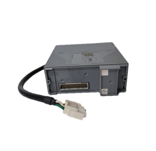
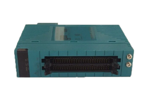
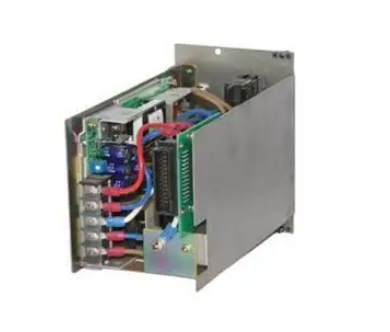
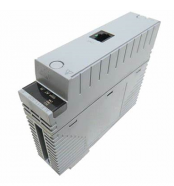
YASKAWA U1000 series 24V power supply options (PS-U10L/PS-U10H)
One letter screwdriver: blade thickness 0.4mm, blade width 2.5mm, used for wiring operation of option terminal block TB1;
Wire stripping pliers: used to strip the insulation layer of cables to ensure good contact between the wiring terminals;
Wrench: Open end wrench, ring wrench or ratchet wrench (diameter 6mm), used to tighten bolts, the tightening torque should be controlled at 0.5-0.7N · m 🔶 2-109;
Attention: The document does not include cable pre-processing tools (such as crimping pliers), and users need to prepare them themselves.
2. Classification of installation methods and operating steps
The document categorizes installation methods into six types, A-F, based on the differences in drive models. The core differences lie in the option fixing method (only screws/screws+studs), cable connection interface (CN1 direct connection/CN19 adapter), and installation position. The following are the key information and general steps for each type of method:
(1) Installation method classification and driver adaptation
Installation method: Adapt to driver model (example) Fixed method: Cable connection interface corresponds to document page number
A U1000 2 0028-2 0081, 4 0011-4 0077; U1000L 20028-20068; Z1000U 2 0028-2 0081 M3 screw option only, CN1 direct connection to driver reserved interface 22
B U1000 2 0104, 2 0130, 4 0096, 4 0124; U1000L 2 0081, 2 0104; Z1000U 2 0104, 2 0130 only M3 screw option CN1 direct connection to driver reserved interface 25
C U1000 2 0154, 2 0192, 4 0156, 4 0180; Z1000U 2 0154, 2 0192 screw+stud option CN1 connected to driver CN19 28 via cable A
D U1000 2 0248, 4 0216, 4 0240; Z1000U 2 0248, 4 0216 screw+stud options CN1 connected to driver CN19 31 via cable B
E U1000 40302-40414; Z1000U 4 0302-4 0414 screw+stud option CN1 connected to driver CN19 34 via cable C
F U1000 4A0477-4A0930; Z1000U 4A0477-4A0930 screw+stud option CN1 connected to driver CN19 37 via cable B
(2) General installation steps (taking method A as an example, differences in other methods have been marked)
Power off and discharge: Disconnect all power sources from the drive, wait for the internal capacitor to discharge (at least 5 minutes until the CHARGE indicator light on the drive goes out), confirm that there is no dangerous voltage, and then remove the digital operator (F), front cover (E), and terminal cover (G). The removal steps should refer to the manual provided with the drive;
Option fixing: Use the M3 screw inside the package to fix the option in the designated position of the driver (refer to Figure 4 in the document for the position), ensuring that it is firmly fixed and not loose;
Cable connection: Pull out the loose end of the reserved connection cable for the driver, insert it into the CN1 interface of the option, pay attention to the interface direction, and reverse insertion may damage the connector or driver;
Cover plate reset: Reinstall the driver front cover, terminal cover, and digital operator to ensure that the cables are not squeezed by the cover plate and to avoid insulation layer damage causing short circuits;
External power supply wiring: Go to the "Wire the Option" section on page 40 of the document and connect an external 24V power supply to the option terminal block TB1 (terminal definition: 24=+24VDC input, 0=0V, FE=ground). The wiring steps are as follows:
Loosen the TB1 terminal screw with a straight screwdriver;
Peel off the insulation layer of the cable (with a bare length of about 5.5mm, to avoid the wire ends from unraveling);
Insert the cable into the corresponding terminal and tighten the screw (torque 0.22-0.25N · m);
Wrap the cable shielding layer with heat shrink tubing or electrical tape to avoid short circuits caused by contact with other circuits 🔶 2-393;
(3) Special installation requirements (for C-F method)
Fixed difference: The C-F method requires the installation of screws (tighten with a 6mm wrench, torque 0.5-0.7N · m) first, and then fix the option with screws;
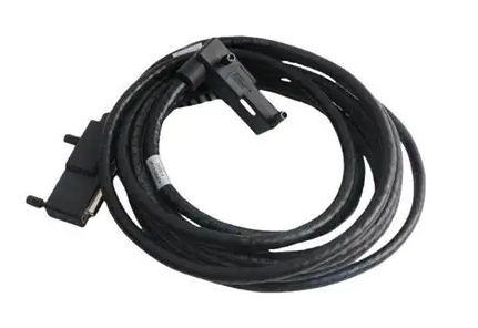
Cable differences: C method uses connection cable A, D/F method uses connection cable B, E method uses connection cable C, and the cables need to be sorted according to the document diagram (such as Figure 23, 27) and fixed with zip ties to avoid cable entanglement or compression.
3. Key wiring specifications
Power requirements: The external 24V power supply must be UL Listed Class 2 certified (or equivalent) to avoid the risk of electric shock or fire caused by the use of non certified power supplies. The power supply must be able to provide at least 3A current (the instantaneous current when the option is powered on is twice the conventional value, lasting for about 0.5 seconds);
Cable specifications: Shielded twisted pair cables are required for control cables, with a recommended wire diameter of 0.75mm ² (18AWG). The suitable wire diameter range for single strand cables is 0.25-1.5mm ² (24-16AWG), and the suitable wire diameter for crimping terminals is 0.25-0.5mm ² (24-20AWG);
Shielding treatment: The cable shielding layer needs to be grounded at one end (connected to the driver grounding terminal) to avoid circulating current caused by double ended grounding, and the grounding area should be as large as possible (refer to Figure 40 in the document);
- EMERSON
- Honeywell
- CTI
- Rolls-Royce
- General Electric
- Woodward
- Yaskawa
- xYCOM
- Motorola
- Siemens
- Rockwell
- ABB
- B&R
- HIMA
- Construction site
- electricity
- Automobile market
- PLC
- DCS
- Motor drivers
- VSD
- Implications
- cement
- CO2
- CEM
- methane
- Artificial intelligence
- Titanic
- Solar energy
- Hydrogen fuel cell
- Hydrogen and fuel cells
- Hydrogen and oxygen fuel cells
- tyre
- Chemical fiber
- dynamo
- corpuscle
- Pulp and paper
- printing
- fossil
- FANUC
- Food and beverage
- Life science
- Sewage treatment
- Personal care
- electricity
- boats
- infrastructure
- Automobile industry
- metallurgy
- Nuclear power generation
- Geothermal power generation
- Water and wastewater
- Infrastructure construction
- Mine hazard
- steel
- papermaking
- Natural gas industry
- Infrastructure construction
- Power and energy
- Rubber and plastic
- Renewable energy
- pharmacy
- mining
- Plastic industry
- Schneider
- Kongsberg
- NI
- Wind energy
- International petroleum
- International new energy network
- gas
- WATLOW
- ProSoft
- SEW
- wind
- ADVANCED
- Reliance
- YOKOGAWA
- TRICONEX
- FOXBORO
- METSO
- MAN
- Advantest
- ADVANCED
- ALSTOM
- Control Wave
- AB
- AMAT
- STUDER
- KONGSBERG
- MOTOROLA
- DANAHER MOTION
- Bently
- Galil
- EATON
- MOLEX
- Triconex
- DEIF
- B&W
- ZYGO
- Aerotech
- DANFOSS
- KOLLMORGEN
- Beijer
- Endress+Hauser
- MOOG
- KB
- Moxa
- Rexroth
- YAMAHA
- Johnson
- Westinghouse
- WAGO
- TOSHIBA
- TEKTRONIX
- BENDER
- BMCM
- SMC


Email:wang@kongjiangauto.com

