
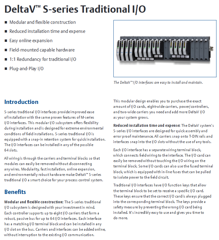
Emerson DeltaV™ S-series Traditional I/O
Module Category Core Usage Typical Model Example Key Features
The digital input (DI) module collects discrete signals from industrial sites (such as sensor and limit switch status), converts them into system recognizable digital signals SDI810 and SDI820, supports dry/wet contact input, has photoelectric isolation function, strong anti-interference ability, and some models support "event capture" (such as edge detection)
Emerson DeltaV™ S-series Traditional I/O
Overview of S Series I/O Module Core
Product series classification
The S series I/O modules are divided into four categories based on "signal type" and "functional characteristics". The core uses and typical models of each module are shown in the table below:
Module Category Core Usage Typical Model Example Key Features
The digital input (DI) module collects discrete signals from industrial sites (such as sensor and limit switch status), converts them into system recognizable digital signals SDI810 and SDI820, supports dry/wet contact input, has photoelectric isolation function, strong anti-interference ability, and some models support "event capture" (such as edge detection)
The digital output (DO) module receives control instructions from the system output and drives actuators (such as solenoid valves and indicator lights) to operate. SDO810 and SDO820 provide two types of outputs: transistor output and relay output. The transistor output has a fast response (microsecond level) and the relay output is resistant to high voltage (suitable for high-power loads)
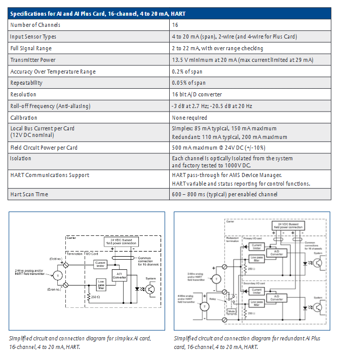
The Analog Input (AI) module collects continuously changing analog signals (such as 4-20mA/0-10V signals output by temperature, pressure, and flow sensors), performs signal conditioning and AD conversion. SAI810 and SAI830 support single ended/differential input, with a maximum resolution of 16 bits, and have cold end compensation (thermocouple input model) and signal filtering functions to reduce on-site noise interference
The Analog Output (AO) module converts the digital control signals output by the system into analog signals (4-20mA/0-10V), and controls analog actuators such as regulating valves and frequency converters. SAO810 and SAO820 have high output accuracy (error ≤± 0.1% of full scale), support "manual output" function (fixed values can be output without system instructions during debugging), and have short-circuit protection
Common technical characteristics
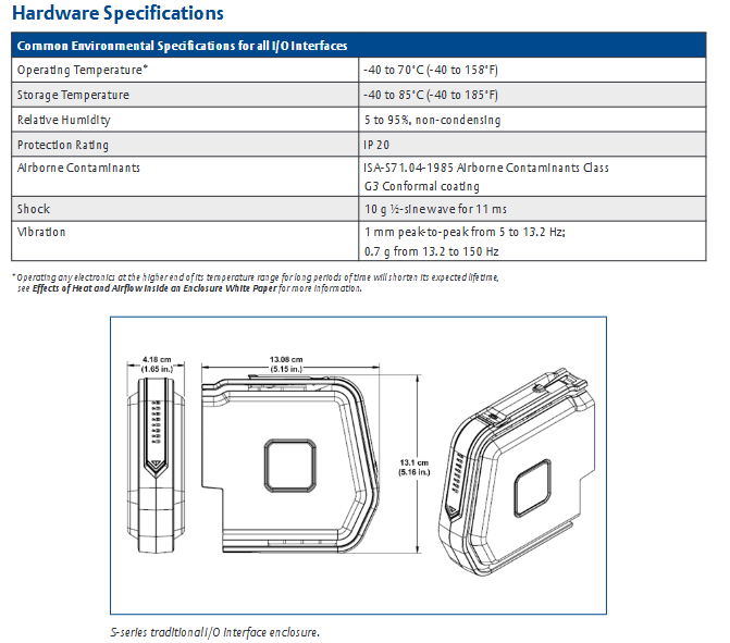
High reliability design: All modules use "industrial grade components" with a working temperature range covering -40 ℃~70 ℃ and a humidity tolerance range of 0~95% (non condensing). Some modules have an IP20 protection level (suitable for installation in control cabinets) and are suitable for harsh industrial environments.
Isolation and anti-interference: The module adopts "photoelectric isolation" or "magnetic isolation" technology internally, and the input/output circuit is isolated from the system power circuit (isolation voltage ≥ 2500V DC), effectively suppressing on-site common mode interference and series mode interference, and ensuring signal transmission stability.
Hot swappable function: Supports "online hot swappable". When replacing modules, the system power does not need to be cut off, only the connection between the module and the base needs to be disconnected, reducing system downtime and improving operation and maintenance convenience (some early models need to confirm whether this function is supported, please refer to the specific model manual).
Diagnosis and status indication: Each module is equipped with LED status indicator lights (such as "power normal", "signal normal", "fault alarm"), which can intuitively judge the operating status of the module; Simultaneously supporting "remote diagnosis", monitoring the real-time status of modules (such as channel faults and overloads) through the DeltaV/Ovation system, and generating diagnostic reports.
Key module technical specifications
Core parameters of digital I/O module
Digital Input (DI) Module:
Input signal type: dry contact (no power supply), wet contact (external power supply, such as 24V DC).
Input voltage range: 18~30V DC (wet contact), dry contact supports "contact closing resistance ≤ 10 Ω, open circuit resistance ≥ 1M Ω".
Response time: fastest 1ms (high-speed DI models, such as SDI820), regular models ≤ 10ms.
Number of channels: A single module supports 8/16 inputs, with channels isolated from each other (some models use group isolation, such as every 4 channels).
Digital Output (DO) Module:
Output types: transistor output (24V DC, maximum load current 0.5A/channel), relay output (250V AC/30V DC, maximum load current 2A/channel).
Output protection: The transistor output has "short-circuit protection" (automatic current limiting in case of overload), and the relay output has "mechanical life ≥ 1 million times" (no load) and "electrical life ≥ 100000 times" (rated load).
Number of channels: A single module supports 8/16 outputs, and some models of relay output modules support "normally open/normally closed" configurable.
Simulate the core parameters of the I/O module
Analog Input (AI) Module:
Input signal types: current signal (4-20mA, 0-20mA), voltage signal (0-5V, 0-10V), thermocouple (J/K/T/E/R/S/B type), thermistor (RTD, Pt100, Cu100).
Resolution: The current/voltage input is 16 bits, and the thermocouple/RTD input is 18 bits (some high-precision models).
Accuracy: Full scale error ≤ ± 0.1% (25 ℃ environment), temperature drift ≤ ± 0.005% full scale/℃.
Sampling rate: Single channel up to 100Hz (high-speed AI models), regular models ≤ 50Hz, supports configurable "channel scanning period" (such as 100ms/200ms).
Analog Output (AO) module:
Output signal types: current signal (4-20mA, load resistance ≤ 500 Ω), voltage signal (0-10V, load resistance ≥ 1k Ω).
Resolution: 16 bits.
Accuracy: Full scale error ≤ ± 0.1% (25 ℃ environment), output ripple ≤ 10mV (peak to peak).
Response time: From 0% to 100% full-scale output ≤ 100ms (current output), ≤ 50ms (voltage output).
Installation and Configuration Guide
Hardware installation process
Installation environment requirements: The module needs to be installed in a standard 19 inch industrial control cabinet, avoiding direct sunlight, dust, corrosive gases, and severe vibrations; The control cabinet needs to reserve a heat dissipation space (with a distance of ≥ 50mm between the top and bottom of the module). If the ambient temperature exceeds 55 ℃, a heat dissipation fan or air conditioner should be equipped.
Installation steps:
First, fix the I/O base (matching the module model) onto the DIN rail of the control cabinet, ensuring that the base is securely installed and not loose.
Connect the power cable (usually 24V DC, pay attention to positive and negative polarity) and communication cable (connected to the I/O link of the DeltaV/Ovation system, such as PROFIBUS, EtherNet/IP) to the base.
Align the module with the card slot on the base, insert it vertically and press it until it makes a "click" sound, and confirm that the module is in good contact with the base (when hot plugging, the signal circuit of the module needs to be disconnected first before plugging).
Connect on-site signal lines: Digital signals use shielded twisted pair cables (with a single end grounded on the shielding layer), while analog signals use shielded twisted pair cables (with both ends grounded on the shielding layer) to avoid parallel laying with power cables (spacing ≥ 300mm).
System configuration steps
Software tool: Use DeltaV Explorer (adapted to DeltaV system) or Ovation Configuration Studio (adapted to Ovation system) for module configuration.
Configuration process:
Add the "S series I/O module" to the software, select the corresponding module model (such as SDI810, SAI830), and assign a unique "module address" (consistent with the hardware dip switch settings to avoid address conflicts).
Configure channel parameters:
Digital input module: Set the "input type" (dry/wet contact), "edge detection" (rising/falling edge), and "filtering time" (such as 1ms/10ms to suppress noise).
Digital output module: Set the "output type" (transistor/relay) and "fault handling" (such as output hold/reset in case of fault).
Analog input module: Set the "signal type" (4-20mA/Pt100/J thermocouple), "range" (such as 4-20mA corresponding to 0-100kPa pressure), and "cold end compensation method" (internal compensation/external compensation, thermocouple input).
Analog output module: Set the "signal type" (4-20mA/0-10V), "range", and "manual output value" (for debugging purposes).
Download the configuration file to the module, and after completion, monitor the module's "online status" through software to confirm that there are no configuration errors (such as "address conflicts" or "signal mismatches").
Functional characteristics and application scenarios
Core functional highlights
Signal conditioning function: The analog I/O module has a built-in "signal conditioning circuit" that can amplify and filter weak signals collected on site (such as mV level signals from thermocouples) to reduce noise interference; Simultaneously supporting "disconnection detection" (such as triggering a fault alarm when the RTD is open or the current signal is disconnected).
Redundancy configuration support: Some key modules (such as analog input and digital output modules) support "1:1 redundancy", which means that the main module and backup module run simultaneously. When the main module fails, the backup module automatically switches (switching time ≤ 100ms) to ensure that the control circuit is not interrupted. This is suitable for safety critical scenarios (such as emergency shutdown systems in petrochemicals).
System Integration: The module seamlessly integrates with the DeltaV/Ovation system, supporting "global database" sharing. The signals collected by the module can be directly used for the system's control algorithms, alarm logic, and historical data storage; Simultaneously supporting the OPC protocol, it can communicate with third-party systems (such as MES production execution systems) to achieve data exchange.
Safety certification: Some modules have passed "ATEX certification" and "IECEx certification" and are suitable for explosive hazardous environments (such as Zone 2, Class I Division 2); Simultaneously complying with the "EN 61000" electromagnetic compatibility (EMC) standard, it has strong resistance to electromagnetic radiation and electrostatic discharge.
Typical application scenarios
Petrochemical industry: used to collect temperature (thermocouple/RTD input) and pressure (4-20mA input) signals of reaction vessels, drive the action of feed valves and discharge valves through digital output modules, and control the opening of regulating valves through analog output modules to achieve precise control of the reaction process.
Power industry: Suitable for Ovation control system in thermal power plants, collecting steam pressure and water level of boilers (4-20mA signal from differential pressure transmitter), controlling the speed of feed pumps through analog output module, and monitoring the operating status of fans and pumps through digital input module (such as overload alarm).
Water treatment industry: The digital input module collects the status of liquid level switches and flow switches, the analog input module collects signals from water quality sensors (such as pH and turbidity), and the digital output module drives solenoid valves and water pumps to achieve automated start stop and regulation of the water treatment process.
Fault diagnosis and maintenance
Common faults and troubleshooting methods
The document provides a "fault diagnosis flowchart" and provides troubleshooting steps for typical module faults. The core fault types and solutions are as follows:
Possible causes and solutions for fault phenomena
Module "power light not on" 1. The base power cable is not properly connected or disconnected; 2. Abnormal power supply voltage (such as below 18V DC); 3. Internal power failure of the module: 1. Check the connection of the power cable (whether the positive and negative poles are reversed); 2. Measure the power supply voltage with a multimeter to ensure it is within the range of 18-30V DC; 3. Replace the module and test if it returns to normal
Digital input module "no signal input" 1. On site signal line breakage or poor contact; 2. Input type configuration error (such as configuring dry contacts as wet contacts); 3. The filtering time is set too long. 1. Check the continuity of the on-site signal line (measure the contact resistance with a multimeter); 2. Verify that the "input type" configured in the software matches the actual wiring; 3. Reduce filtering time (such as changing from 10ms to 1ms)
Analog output module "no output signal" 1. Output channel fault; 2. Range configuration error (such as 4-20mA configured as 0-10V); 3. Load resistance exceeds the rated range. 1. Switch to "manual output" mode and observe if there is any output; 2. Verify the range configuration and re download the configuration file; 3. Measure the load resistance to ensure that the current output load is ≤ 500 Ω and the voltage output load is ≥ 1k Ω
Module "Fault light always on" 1. Channel short circuit (such as load short circuit in analog output module); 2. Module address conflict; 3. Configuration file error: 1. Disconnect the on-site signal line and check if the fault still reports (eliminate the short circuit problem); 2. Verify that the hardware dialing address of the module matches the software configuration address; 3. Download the correct configuration file again
Daily maintenance suggestions
Regular inspection: Check the LED status indicator lights of the module every 3 months to confirm that there are no abnormal alarms; At the same time, check whether the connection between the module and the base is firm, and whether the wiring terminals of the on-site signal line are loose (to avoid poor contact caused by vibration).
Cleaning and maintenance: Clean the surface of the module with dry compressed air (pressure ≤ 0.3MPa) every 6 months to avoid dust accumulation and affect heat dissipation; If there is oil contamination inside the control cabinet, a soft cloth dipped in isopropanol can be used to wipe the module housing (be careful to avoid liquid entering the interior of the module).
Spare parts management: For critical modules (such as redundant analog input modules), it is recommended to reserve 1-2 spare modules, which need to be regularly powered on for testing (every 12 months) to ensure normal performance.
- OMRON
- ABB
- General Electric
- EMERSON
- Honeywell
- HIMA
- ALSTOM
- Rolls-Royce
- MOTOROLA
- Rockwell
- Siemens
- Woodward
- YOKOGAWA
- FOXBORO
- KOLLMORGEN
- MOOG
- KB
- YAMAHA
- BENDER
- TEKTRONIX
- Westinghouse
- AMAT
- AB
- XYCOM
- Yaskawa
- B&R
- Schneider
- KONGSBERG
- NI
- WATLOW
- ProSoft
- SEW
- ADVANCED
- Reliance
- TRICONEX
- METSO
- MAN
- Advantest
- STUDER
- DANAHER MOTION
- Bently
- Galil
- EATON
- MOLEX
- DEIF
- B&W
- ZYGO
- Aerotech
- DANFOSS
- Beijer
- Moxa
- Rexroth
- Johnson
- WAGO
- TOSHIBA
- BMCM
- SMC
- HITACHI
- HIRSCHMANN
- Application field
- XP POWER
- CTI
- TRICON
- STOBER
- Thinklogical
- Horner Automation
- Meggitt
- Fanuc
- Baldor
- SHINKAWA
- Other Brands
- UniOP
- KUKA
- Iba
- Beckhoff
- ADLINK
-
 ETEL DSCDL332-131C-000A Servo Control Board
 -
 ETEL DSCDP324-322F-000C Dual Motor Driver
 -
 ETEL EA-P2M-400-10/20A Position Controller
 -
 ETEL DSC2P121 and DSO-HIO33 Servo Amplifier Set
 -
 ETEL EA-P2M-400-15/40A AccurET Drive
 -
 ETEL EA-P2M-300-07/15A Position Controller
 -
 ETEL EA-P2M-048-05/10A-0100-01 Servo Drive
 -
 ETEL EA-S0M-300-40/80A Servo Drive Guide
 -
 ETEL DSB2P131-111E-000H Digital Servo Amplifier
 -
 ETEL DSCDP334-421-000 Servo Drive Guide
 -
ETEL EA-S0M-300-40 80A-0000-00 Motion Control Module
-
 ETEL UltimET Light Motion Controller EU-LGP-0-0-1000-01 Multi-Axis
 -
 ETEL DSO-RAC601-029 Controller Rack
 -
ETEL DSMAX212-121C-000C Board
-
 ETEL DSCDL132-212B-000C Position Controller
 -
 ETEL TMB0291-050-3TDS-E82 Torque Motor
 -
 ETEL DSMAX212-121-000 Board
 -
 ETEL DSB2P131-111E-000H Digital Servo Controller Amplifier Unit
 -
 ETEL DSB 2S 124-211E-000H Digital Servo Amplifier
 -
 ETEL AccurET EA-P2M-300-4/7.5A-0100-01 Modular Position Controller
 -
 Beckwith Electric M-6280A Digital Capacitor Bank Control
 -
 Beckwith M-2355B Adapter Panel with M-2001C-6SL Tapchanger Control
 -
 Beckwith M-0359 Syncrocloser MOD512
 -
Beckwith Electric M-2001C-6ELFA Tap Changer Controller
-
 Beckwith M-3311A 4-Coil Transformer Protection Relay
 -
 Beckwith M-0124 Terminal Board Adapter Plate Guide
 -
 Beckwith Pride M-0296C 3-Phase Programmable Relay
 -
 Beckwith M-0388 Syncrocloser Check Relay Guide
 -
 Beckwith M-0170A AC Current Relay Guide
 -
Beckwith M-3311 Transformer Protection Relay Guide
-
Beckwith Electric M3310 Integrated Transformer Protection Panel
-
 Beckwith M-0145 First Customer Protector
 -
Beckwith M-0170A AC Current Relay
-
 Beckwith PRIDE M-0296C 3 Phase Programmable Relay
 -
 Beckwith Pride M-0296b 3-Phase Programmable Relay
 -
Beckwith M-0245C High Speed Sync-Check Relay Guide
-
 Beckwith M-0115A AC Parallel Balancing Module
 -
Beckwith M-0389 Voltage Verifier Relay
-
Beckwith M-0115A Parallel Balancing Module
-
 Beckwith M-0389 Voltage Verifier
 -
 Beckwith PRIDE M-0420 Multifunction Relay Protection Module 48VDC
 -
 Beckwith Electric M-3430 Generator Protection Relay
 -
 Beckwith Electric M-0067E Tapchanger Control
 -
 Beckwith Electric M-0420 Multifunction Relay
 -
Beckwith Electric M-2001D-6L4S20C0S0X Tap Changer Control
-
 Beckwith Electric M3425A-STD1 Generator Protection Relay
 -
Beckwith Electric M-0245C High Speed Sync-Check Relay
-
Beckwith Electric M-3520 Intertie Protection Relay Guide
-
Beckwith Electric M-2001C-6SL Tap Changer Control
-
Beckwith Electric M-2001C Tap Changer Control Guide
-
Beckwith 35-12-635 Generator Protection Keypad Interface
-
Beckwith Electric P-2216 Generator Protection Main Board
-
 Beckwith Electric M-2293 Tap Changer Control Guide
 -
 Beckwith M-4272-6AB1EH0 Integrated Synchronizing Motor Bus Transfer
 -
Beckwith Electric M-4272 Motor Bus Transfer 60-140V 50/60Hz
-
Beckwith Electric M-2001B TapChanger Control
-
Beckwith Electric M-0193B Synchrocloser Unit
-
Beckwith Electric M-0115A AC Parallel Balancing Module
-
Beckwith Electric M-0169A Current Transformer
-
 Beckwith Electric P-1939 Generator Protection Annunciator Panel
 -
Beckwith Electric M-3311A Transformer Protection Relay Guide
-
Beckwith Electric M-0245B High Speed Sync-Check Relay
-
Beckwith Electric M3420 Generator Protection Relay
-
 Beckwith M-0193B Syncrocloser Unit
 -
 Beckwith Electric M-520 Intertie Protection Relay
 -
 Beckwith Electric M-3425A Generator Protection Relay
 -
Beckwith M-3425 Integrated Generator Protection Relay
-
Beckwith M-0115A Parallel Balancing Module
-
Beckwith Electric M-4272 Integrated Synchronizing Motor Bus Transfer
-
Beckwith Electric M-3420 Generator Protection System
-
Beckwith M-0193 Syncrocloser Unit
-
 Basler Electric DECS-250-CN1SN1N Digital Excitation Control System
 -
 Basler Electric BE1-700 E0N2X1N Digital Protective Relay
 -
 Basler Electric SR4A-2B15B3A Static Voltage Regulator 120VAC 50/60Hz
 -
 Basler Electric 9261402111 PCB Control Board 9346000033
 -
 Basler Electric BE28053-002 Transformer BE28053002
 -
 Basler Electric BE3-25A Auto Synchronizer B1D Sync Module
 -
 Basler Electric BE3-GPR Generator Protective Relay
 -
 Basler Electric SCP-250-G-60 VAR Power Factor Controller 9 1100 00 109
 -
 Basler Electric BE3-32-1S1N1 Reverse Power Relay 277V 5A
 -
 Basler Electric ACA1300-60GM Area Scan Camera 106200-17
 -
 Basler Electric UFOV 260 A Protection Module Specs
 -
 Basler Electric BE03303001 Control Module
 -
Basler Electric BE3-GPR-P1BVSF Generator Protective Relay
-
 Basler Electric BE1-87G Solid State Protective Relay Guide
 -
 BASLER ELECTRIC BE1-60 VOLTAGE BALANCE RELAY T176884
 -
 Basler Electric BE1-32R Protective Relay
 -
 Basler Electric 9022900-103 Transformer 6-7VA 60Hz
 -
 Basler Electric BE1-59-A4E-E1K-B1S3F Overvoltage Relay
 -
 Basler Electric KR2FF-M Voltage Regulator 9 1163 00 103
 -
 Basler Electric UFOV 260 A Protective Module
 -
 Basler Electric PCB Assembly 9059701100 919620
 -
 Basler Electric SR8A2B01A3E Static Voltage Regulator
 -
 Basler Electric SSR125-12 Static Voltage Regulator 9185900102
 -
 Basler Electric SSR 63-12 Static Voltage Regulator 600VAC
 -
 Basler Electric BE1-60 Solid State Protective Relay
 -
 Basler Electric BE3-47N/27-3A4N2 Voltage Relay 9320400101
 -
 Basler Electric BE1-59 Over Voltage Relay
 -
 Basler Electric DECS100-B15 Automatic Voltage Regulator
 -
 Basler Electric PRS250 Veri-Sync Relay 9088800102
 -
Basler Electric BE25927001 Current Transformer 1:34 Amp
-
Basler Electric 9170818100 Generator Differential Relay
-
 Basler Electric BE1-59N Solid State Ground Fault Overvoltage Relay
 -
 Basler Electric 1783 DC Current Transformer Coil 1200:5A
 -
Basler Electric BE1-67 Ground Directional Overcurrent Relay
-
 Basler Electric UFOV-260A Underfrequency Overvoltage Module
 -
 Basler Electric BE10493001 Control Module
 -
Basler Electric SSR125-12 Static Voltage Regulator Guide
-
 Basler Electric BE1810/U-2 Solid State Frequency Relay Guide
 -
 Basler Electric 9105100106 UFOV-250A Protector Guide
 -
 Basler Electric MOC2199 9072300-335 Relay Module Guide
 -
 Basler Electric 9289902106 Circuit Board
 -
Basler Electric BE1-32R Protective Relay A1E E1P BOS1P
-
 Basler Electric RAL6144-16GM GigE Line Scan Camera with Lens
 -
 Basler Electric BE3-49R-5I5A1 Temperature Relay
 -
 Basler Electric BE1-32R Power Relay B3E E1R A0N1F
 -
 Basler Electric SR4A2B06B3A Static Voltage Regulator Features
 -
 Basler Electric 9121000106 Manual Voltage Control MVC Guide
 -
Basler Electric SR32A-2B15B3E Static Voltage Regulator
-
 Basler Electric SR4A2B06B3A Static Voltage Regulator Guide
 -
Basler Electric 801A193F02 Hammond Transformer Module
-
 Basler Electric BE1-24 Volts Per Hertz Relay A1E F1J D1S0F
 -
 Basler Electric AEC63-7 Analog Excitation Controller 220-277V
 -
Basler Electric BE132R Power Relay T245579
-
 Basler Electric MVC 108 Manual Voltage Control 90 37000 102
 -
 Basler Electric 9022900-103 Control Transformer 6-7VA 60Hz
 -
 Basler Electric BE1-79M Plug Adapter 9170111102
 -
 Basler Electric 9 2007 00 100 Current Boost System CBS 305


