
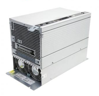
Tektronix AWG70000 series arbitrary waveform generator
Compliance certification: Complies with EN 61010-1, UL 61010-1, CSA C22.2 No. 1010.1 safety standards to ensure compliance in industrial use.
Tektronix AWG70000 series arbitrary waveform generator
Product Overview
Product coverage: AWG70000 series full models (such as AWG70001 single channel, AWG70002 dual channel), supporting software version 7.0 and above.
Compliance certification: Complies with EN 61010-1, UL 61010-1, CSA C22.2 No. 1010.1 safety standards to ensure compliance in industrial use.
Remote control setup: Ethernet and GPIB
1. Ethernet control (recommended)
(1) Hardware connection
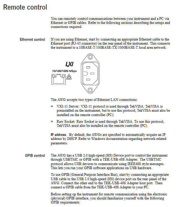
Connect the Ethernet port of the instrument Rear panel to the LAN switch/PC using an RJ-45 Ethernet cable, supporting speeds of 10BASE-T (10Mbps), 100BASE-TX (100Mbps), and 1000BASE-T (1Gbps).
(2) Protocol and Configuration
Protocol type requirements for application scenarios
VXI-11 Server instrument and PC are both equipped with TekVISA standard remote control, with strong compatibility
Both the Raw Socket instrument and PC are equipped with TekVISA high-speed data transmission and low latency
DHCP is enabled by default for IP acquisition, and the IP is automatically obtained from the router. If a fixed IP is required, the laboratory's fixed network environment can be modified through Windows network settings
2. GPIB control (compatible with traditional devices)
(1) Hardware connection
Instrument Rear panel USB 2.0 HS Device port → connect to the host port of TEK-USB-488 adapter;
Connect the GPIB port of the adapter to the GPIB card/interface of the PC using a GPIB cable.
(2) Key configuration rules
Address uniqueness: Each device on the bus must be assigned a unique address (1-30), which cannot be duplicated;
Bus limitation: Up to 15 devices can be connected, with 1 device required every 2 meters (6 feet), and the total cable length should be ≤ 20 meters (65 feet);
Power requirement: At least 2/3 of the equipment should be powered on to avoid signal attenuation;
Topology: Only supports star or linear connections, and prohibits ring/parallel connections.
(3) Address modification steps
Instrument end: Go to Utilities → System → GPIB Address, set a new address (default 1);
Restart adapter: Disconnect and reconnect the TEK-USB-488 adapter to ensure the new address takes effect.
Command syntax specification: SCPI standard and execution mechanism
1. Core grammatical symbols
Example of symbol meaning
<>Defined element (required)<wfm_name>(waveform name)
Defined as<Block>::=#<NZDig><Dig>... (Block Data Definition)
`XOR (choose one) ON OFF (choose one)
{} Required group (choose one) ` {INTernal EXTernal} ` (required internal/external)
[] Optional section [:]<Header>(colon optional)
... The preceding elements can be repeated<Argument>[,<Argument>...] (multi parameter)
() Comment #<NZDig>(non-zero digits)
2. Command and Query Structure
(1) Command (modify settings/execute actions)
Format: [:]<Header>[<Space><Argument>[<Comma><Argument>...]
Example: CLOCk: SURce INTernal (set clock source to internal)
(2) Query (Get Status/Data)
Format: [:]<Header>? [<Space><Argument>[<Comma><Argument>...]]
Example: CLOCk: SURce? (Query the current clock source)
3. Parameter types and rules
Example of Parameter Type Description
Boolean 0/OFF (false), 1/ON (true) AWGControl: DLOading: ENABle 1 (enable dynamic loading)
Discrete fixed options (such as MIN/MAX) FGEN: CHANnel1: AMPCrude MAX (amplitude set to maximum)
Numerical values (NR1/NR2/NR3/NRf) NR1 (integer, such as 123), NR2 (decimal, such as 12.3), NR3 (scientific counting, such as 1.23E3), NRf (flexible format) CLOCk: SRATE 25E9 (sampling rate 25GS/s)
String needs to be enclosed in single/double quotes MMEMory: OPEN "C: waveform. wfmx" (load file)
Arbitrary Block: Binary data block in the format of #<NZDig><Dig>...<DChar>... WLILD: WAVeform: DATA "TestWfm", # 41024xxxx... (transmitting 1024 points of data)
4. Command execution mechanism
(1) Three types of commands
Example of Type Characteristics
Execute the next command OUTPut1: STATe ON only after the previous command is completed; OUTPut2: STATe ON (First turn on CH1, then turn on CH2)
During the execution of the blocking command, other commands are prohibited, which takes a long time. CALibration [: ALL] (full calibration, waiting for completion)
Overlapping commands can be executed concurrently with other commands, and it is necessary to manually ensure the completion of DIAGnostic: STARt (diagnostic startup, requires OPC)? Confirmation completed)
(2) Key Execution Rules
Abbreviation rule: Commands can be abbreviated, with the capitalized part being the abbreviation core (such as TRIGger: LEVel → TRIG: LEV);
Splicing rules: Use; Splicing multiple commands, different root nodes need to add: (such as TRIG: SUR EXT; :SOUR1:RMODe TRIG);
Termination symbol: When sending commands, EOI (last byte assertion) should be used as the termination symbol, and the instrument response should be terminated with LF+EOI;
Clear command: * CLS clears all event registers and queues, Device Clear (DCL) resets the command reception status.
Detailed explanation of core command group (selected high-frequency group)
1. Clock group (CLOCk): controls sampling rate and synchronization
- OMRON
- ABB
- General Electric
- EMERSON
- Honeywell
- HIMA
- ALSTOM
- Rolls-Royce
- MOTOROLA
- Rockwell
- Siemens
- Woodward
- YOKOGAWA
- FOXBORO
- KOLLMORGEN
- MOOG
- KB
- YAMAHA
- BENDER
- TEKTRONIX
- Westinghouse
- AMAT
- AB
- XYCOM
- Yaskawa
- B&R
- Schneider
- KONGSBERG
- NI
- WATLOW
- ProSoft
- SEW
- ADVANCED
- Reliance
- TRICONEX
- METSO
- MAN
- Advantest
- STUDER
- DANAHER MOTION
- Bently
- Galil
- EATON
- MOLEX
- DEIF
- B&W
- ZYGO
- Aerotech
- DANFOSS
- Beijer
- Moxa
- Rexroth
- Johnson
- WAGO
- TOSHIBA
- BMCM
- SMC
- HITACHI
- HIRSCHMANN
- Application field
- XP POWER
- CTI
- TRICON
- STOBER
- Thinklogical
- Horner Automation
- Meggitt
- Fanuc
- Baldor
- SHINKAWA
- Other Brands
- UniOP
- KUKA
- Iba
-
 B&R X20CP1486 Controller Manual
 -
 Siemens 6ES7134-4GB51-0AB0 Module Manual
 -
 Schneider LMC201CAA10000 Controller Manual
 -
 Fuji Electric NP1L-RS4 Module Guide
 -
 Mitsubishi FX2N-16LNK-M Master Guide
 -
 Yaskawa SGDM-08ADA SGMAH-08AAA41 Manual
 -
 Fanuc A20B-0008-0470 Board Manual
 -
 Calpeda T 70/B Module Specifications
 -
 Eurotherm TC3000 Power Drive Specifications
 -
 Mitsubishi QJ71GP21S-SX Module Manual
 -
 B&R X20AI4622 Analog Input Module 4 Channels
 -
 Siemens Simatic S5 PLC I/O and CPU Modules
 -
 Tel 38950 PCB Board 5044-000171-11 AP9Z-2033A
 -
 Sanyo PLC-XTC50L Multimedia Projector
 -
 Siemens 6GK7243-5DX30-0XE0 CP 243-5 AS-Interface
 -
 Omron V680-CA5D02-V2 RFID Controller
 -
 Pilz 570640 PSEN SL-1.0P Safety Switch
 -
 Schneider LXM62DD27D21000 Servo Drive
 -
 Pilz 401112 PITswitch en1.1a-5m-s Emergency Stop Switch
 -
 Pilz 774350 P2HZ X3 Safety Relay
 -
 Siemens S30810-Q1113-X4-6/02 EWSD Module Board
 -
 Honeywell 30751044-008 ROM PLC Control Board
 -
 Allen-Bradley 440R-W23219 MSR310P Safety Relay
 -
 Siemens 6GK5204-2BB10-2AA3 Industrial Ethernet Switch
 -
 Siemens YSU C32353ADDAGS C98043 PC Board
 -
 Schneider TM241CEC24T PLC Controller Modicon M241
 -
 VARIAN E15000591 PLC PCB Assembly 132102
 -
 Schneider Electric HMIG3U PLC Controller Module
 -
 Siemens 6ES7148-4FC00-0AB0 ET200 IO Module
 -
 Siemens A5E30484420 Simatic IPC Redundant PSU
 -
 Allen Bradley 1771-A3B Chassis Manual
 -
 Schneider BMEH586040 Processor Manual
 -
 Mitsubishi GT2508 Graphic Panel Manual
 -
 Mitsubishi FX2N-16LNK-M Link Module Manual
 -
 Beckhoff EL3011 Analog Terminal Manual
 -
 Siemens 6SN1145-1AA01-0AA1 Infeed Manual
 -
 Proface SP5000 Series Display Specifications
 -
 NUM 0204203001 Axes Board Manual
 -
 Square D LV434001 Ethernet Interface Manual
 -
 Omron NA5 Series HMI Module Specifications
 -
 ABB 57619104E Inverter PCB Control Board
 -
 Allen-Bradley 100-E205ED11 MCS-E Contactor 205A
 -
 Omron NS12-TS01-ECV2 Series Operation Panel
 -
 Allen-Bradley 440R-EM4R2 Guardmaster Safety Relay
 -
 Omron CS1D-DPL01 Duplex System PLC Module
 -
 Beckhoff CX2030-0115 Embedded PC Controller
 -
 ABB Pluto S20 v2 Cfs Safety PLC 2TLA020070R4700
 -
 B&R X20AT4222 Analog Input Module RTD
 -
 Inovance H3U-3624MT PLC Controller
 -
 GE Fanuc IC698CPE010 PLC CPU Module
 -
 Texas Instruments Siemens 505-6208-A Analog Input Module
 -
 VDISP 0035416 Card Module Industrial Display Controller
 -
 HITACHI TX09D80VM3CCA 3.5 Inch LCD Screen 240x320
 -
 Siemens 545 555 1105 1106 PLC Controller
 -
 H2-ECOM100 PLC Communication Module Ethernet
 -
 B&R X20CS1012 PLC Module X20 CS 1012
 -
 Siemens 6ES7212-1HF40-0XB0 PLC Module 24VDC
 -
 Omron C120-0C222 IO Module 3G2A6-0C222
 -
 Electromatic Denmark PLC TYPE 200816 Industrial Controller
 -
 SANYO PLC-XTC50L Projector 50-60Hz LCD Installation
 -
 LTi SO84.450 Servo Drive Controller - 450A Three-Phase BG7
 -
 LTi SO84.375 Servo Drive Controller - 375A Three-Phase BG7
 -
 LTi SO84.325 Servo Drive Controller - 325A Three-Phase BG7
 -
 LTi SO84.250 Servo Drive Controller - 250A Three-Phase BG7
 -
 LTi SO84.170 Servo Drive Controller - 170A Three-Phase BG6a
 -
 LTi SO84.143 Servo Drive Controller - 143A Three-Phase BG6a
 -
 LTi SO84.110 Servo Drive Controller - 110A Three-Phase BG6
 -
 LTi SO84.090 Servo Drive Controller - 90A Three-Phase BG6
 -
 LTi SO84.072 Servo Drive Controller - 72A Three-Phase BG5
 -
 LTi SO84.060 Servo Drive Controller - 60A Three-Phase BG5
 -
 LTi SO84.045 Servo Drive Controller - 45A Three-Phase BG5
 -
 LTi SO84.032 Servo Drive Controller - 32A Three-Phase BG4
 -
 LTi SO84.024 Servo Drive Controller - 24A Three-Phase BG4
 -
 LTi SO84.020 Servo Drive Controller - 20A Three-Phase BG3
 -
 LTi SO84.016 Servo Drive Controller - 16A Three-Phase BG3
 -
 LTi SO84.012 Servo Drive Controller - 12A Three-Phase BG2
 -
 LTi SO84.008 Servo Drive Controller - 8A Three-Phase BG2
 -
 LTi SO84.006 Servo Drive Controller - Three-Phase 230-480V 6A
 -
 LTi SO84.004 Servo Drive Controller - Three-Phase 230-480V 4A
 -
 LTi SO82.004 Servo Drive Controller - Single-Phase 230V 4A
 -
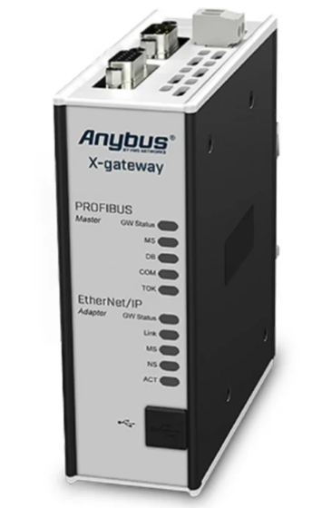 HMS Anybus AB7646-F Gateway Manual
 -
 Schneider ATV930D75N4 Inverter Manual
 -
 Mitsubishi Q2ASHCPU-S1 System Manual
 -
 Fanuc A20B-3300-0319 Board Specification
 -
 Mitsubishi QD60P8-G Counter Module Guide
 -
 Nidec Unidrive M701 Inverter Manual
 -
 ABB AO895 Analog Output Module Guide
 -
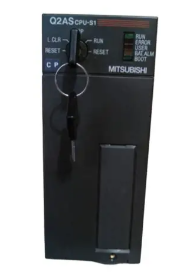 Mitsubishi Q2ASHCPU Controller System Manual
 -
 ABB Pluto S20 v2 Safety PLC Manual
 -
 Omron CJ1W-NC413 Position Module Manual
 -
 B&R X20AI4632 Analog Input Module 4 Channel
 -
 OMRON CS1G-CPU44H Ver. 4.1 CPU Unit PLC
 -
 Beckhoff EL2911-2200 TwinSAFE Logic Terminal for EtherCAT
 -
 Mitsubishi 2D-TZ368 Parallel I/O Interface Card
 -
 Mitsubishi A3ACPU PLC CPU Module for MELSEC A Series
 -
 Mitsubishi NF630-SEW 4P Adjustable Circuit Breaker 300-630A
 -
 Keyence XG-8700L Multi-camera Vision System for Inspection
 -
 Beckhoff C6017-0010 Ultra Compact Industrial PC
 -
 B&R 3AT660.6 PLC Module from Automation Panel Series
 -
 GE F31X300CCHALG2 PC Board with 531X133PRUAPG1 Card
 -
 STMicroelectronics STM32L100R8T6ATR MCU Arm Cortex-M3
 -
 Omron CS1W-CLK13 Controller Link Unit
 -
 Schneider BMENOC0301 Ethernet Communication Module
 -
 HELUKABEL Braids PLC-30 40 E2UK Braided Cable Sleeve
 -
 Pe323 h0102de323a0 PLC I/O Module
 -
 Mitsubishi GT2512-STBA GT2512-STBD HMI 12.1 Inch Touch Screen
 -
 Samsung LTM213UP01 21.3 Inch LCD Monitor Panel
 -
 Allen-Bradley 440R-W23219 Guardmaster Safety Relay
 -
 Beckhoff EL2535 EtherCAT Terminal PWM Output
 -
 HELUKABEL Braids PLC-40 55 E2UK Braided Cable Sleeve
 -
 Allen Bradley 1769-OB16 16-Point Sourcing Output Module
 -
 Balluff BES 516-604-DZ-3 Delay Safety Relay for Industrial Timing
 -
 Siemens 6GK7542-1AX10-0XE0 PROFIBUS Communication Module for S7-1500
 -
 GE IC693BEM340 FIP Controller for Series 90-30 PLC
 -
 OMRON C200HG-CPU63-E Programmable Logic Controller CPU Unit
 -
 Schneider EOCR-PMZ Relay Manual
 -
 Honeywell C36TC0UA21D0 Controller Specifications
 -
 Emerson Ovation VE4001S2T2B4 Input Module
 -
 Omron CJ1M-CPU22 CPU Specifications
 -
 Grundig NEA02 AES 0 Card Specifications
 -
 Omron CJ1W-AD081-V1 Analog Input Specifications
 -
 IDEC FS1A-C21S Safety Controller Manual
 -
 IFM O3D303 Smart 3D Sensor Specifications
 -
 Siemens 6SN1123-1AB00-0BA2 Power Module Guide
 -
 B&R 4PP035.0300-01 Power Panel Manual
 -
 Siemens 6ES7 153-2BA10-0XB0 IM Module
 -
 Beckhoff EL3356-0010 Analog Input Module
 -
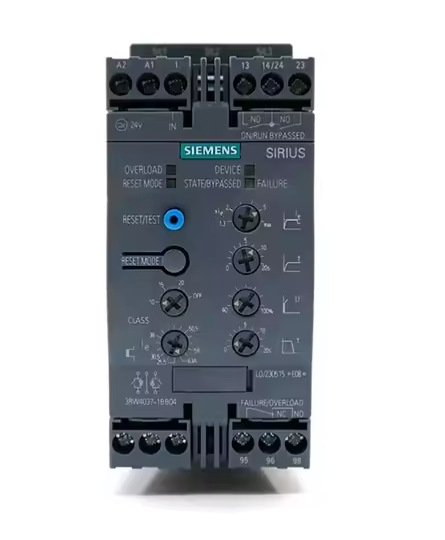 Siemens 3RW4037-1BB04 Soft Starter


