
Watlow PM PLUS ™ PID/Integrated Limit Controller
Watlow PM PLUS ™ PID/Integrated Limit Controller
Product Core Overview
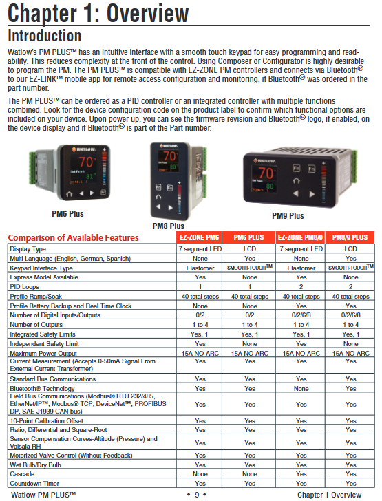
Watlow PM PLUS ™ It is an enhanced PID/integrated limit controller that optimizes user experience and functional scalability while being compatible with the previous generation EZ-ZONE PM controller. The product is positioned as an industrial grade temperature and process control, supporting single/dual PID control loops and integrating functions such as limit control, timing, and curve programming. It is widely used in semiconductor manufacturing, chemical reactions, equipment heating, and other scenarios. Its core advantages include Bluetooth wireless configuration, intuitive touch operation, support for multiple communication protocols, and comprehensive security authentication, which can adapt to the precise control needs in complex industrial environments.
Core features:
Compatibility and Upgradeability: Fully compatible with the wiring and parameter settings of EZ-ZONE PM, can be replaced without hardware modification, and upgraded with smooth touch keyboard, multilingual display (English/German/Spanish) and other operations.
Control capability: Supports PID (including P/PI/PD mode), switch control, curve programming (4 curves, a total of 40 steps), equipped with TRU-TUNE+adaptive algorithm and automatic tuning function to improve dynamic control accuracy.
Communication and wireless functions: Supports Bluetooth (via EZ-LINK mobile application), Modbus RTU/TCP, EtherNet/IP, DeviceNet and other protocols, allowing remote configuration of parameters and monitoring, reducing on-site wiring dependence.
Safety and Certification: Certified by UL, CSA, CE, RoHS, FM, etc., some models support Class 1, Zone 2 hazardous environments, integrate limit control and multiple alarms to ensure equipment and personnel safety.
Product model and core configuration
(1) Model classification and structure
The product is divided into three series based on installation size and function. The core model parameters are defined by a 14 digit configuration code, and the key dimensions are as follows:
Classification, specific specifications, applicable scenarios
Installation size: 1/16 DIN (PM6), 1/8 DIN vertical (PM8), 1/8 DIN horizontal (PM9). Different panel space requirements, 1/16 DIN is suitable for compact scenarios, and 1/8 DIN is suitable for multi parameter display requirements
Core function - PID basic type (C/R/T/J/N): including universal input, curve programming (some models), and timing function
-Integrated limit type (L/M): Additional support for sensor backup, over limit protection, output 4 fixed limit control - Basic type: Single heating/cooling control
-Integrated type: Scenarios that require dual safety protection (such as high-temperature furnaces and hazardous material heating)
The power supply and I/O power supply can be selected from 100-240V AC or 20-28V AC/12-40V DC. The digital I/O supports 2-point or 6-point expansion to adapt to the global power grid. Multiple I/O point models can be connected to external trigger signals (such as emergency stop and start switches)
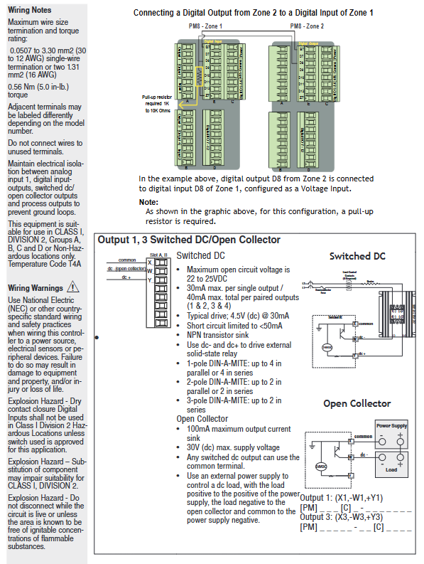
Output types support switch DC, mechanical relay (5A), SSR (0.5A), NO-ARC relay (15A), universal process output (0-10V/4-20mA) - NO-ARC relay: high-power resistive load (such as large heaters)
-Universal process output: signal retransmission to recorder or PLC
(2) Core hardware specifications
Category detailed parameters
Input Characteristics - Universal Input: Thermocouple (J/K/T/E, etc.), RTD (100 Ω/1k Ω), Process Signal (0-20mA/0-10V)
-Input accuracy: ± 0.1% range (typical value), temperature stability ± 100ppm/° C
-Sensor backup: supports dual sensor switching, automatically switches to backup sensor in case of failure
Output Capacity - Maximum Output: 15A NO-ARC Relay (AC Load Only)
-Process output: 0-10V (minimum 1k Ω load) or 4-20mA (maximum 800 Ω load), accuracy ± 20 μ A/± 10mV
Environmental adaptability - Operating temperature: 0-65 ° C (non condensing)
-Protection level: Front panel IP67/IP4X (indoor)
-Anti interference: Compliant with IEC 61000-4 series standards, anti-static and radio frequency interference resistant
Installation and wiring specifications
(1) Installation requirements
Panel opening and fixing
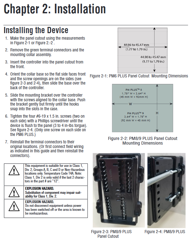
Size standards: 1/16 DIN (PM6) opening 45 × 45mm, 1/8 DIN (PM8/9) opening 45 × 92mm (vertical)/92 × 45mm (horizontal).
Installation steps: Remove the terminal and fixing ring → Insert the controller from the front of the panel → Align the fixing ring and tighten the screws (torque 3-4 in lbs) → Reinstall the terminal.
Environmental restrictions: Avoid corrosive gases and high vibration environments, install vertically to ensure heat dissipation, and reserve a spacing of ≥ 30mm for parallel installation of multiple units.
Power supply and wiring safety
Power adaptation: High power models (1/2) are connected to 100-240V AC, while low-power models (3/4) are connected to 20-28V AC/12-40V DC, and must match the power type indicated on the equipment label.
Wiring specifications: Wire specifications are 12-30 AWG, terminal torque is 5.0 in lb, unused terminals need to be empty, analog input and power/digital signals need to be isolated and wired to avoid grounding loops.
Attention to hazardous environments: Class 1, Zone 2 models (with "12" at the end of the configuration code) require the use of explosion-proof switches. It is prohibited to plug or unplug wiring when powered on, and replacement parts must comply with hazardous environment certification.
(2) Key wiring example
Sensor wiring
Thermocouple: Connect the negative electrode (usually red) to the S1/S2 terminal, and the extension wire should be consistent with the thermocouple material (such as K-type extension wire for K-type).
RTD: 2/3 wire system, 3-wire system needs to ensure that the resistance of the three leads is consistent (≤ 20 Ω), S1 is connected to a white lead to compensate for the lead resistance.
Process signal: 4-20mA signal connected to+R1/- S1 terminal, 0-10V signal connected to+T1/- S1 terminal, requiring separate shielded wiring.
Output and communication wiring
NO-ARC relay: only connected to AC loads (85-264V AC), load current ≤ 15A, prohibited from series use, cycle time ≥ 5 seconds.
Communication wiring: RS-485 uses twisted pair cables (T+/R+connected to B, T -/R - connected to A), and a 120 Ω terminal resistor needs to be added at the end of the bus. The distance between the communication line and the power line should be ≥ 305mm.
Digital I/O: 2-point I/O model (configuration code 2/4) supports dry contact or 3-36V DC input, 6-point I/O model (configuration code C/D/M/N) expandable switch output, with a maximum load of 1.5A per channel.
Operating interface and core functions
(1) User interface
Touch buttons and display
Key functions: Home button (return to home page), left and right buttons (menu navigation), increase and decrease buttons (parameter adjustment), custom function buttons (F1/F2, can set start/stop curves, reset alarms, etc.).
Display mode: default display of process values (such as temperature), set values, and regions, supporting 4 themes (such as white background, high contrast blue background), customizable display parameters (such as output power, remaining time).
Message prompt: Automatically switch display in case of alarm/error, such as "Limit High" or "Input Error". The lock alarm can be cleared by pressing the home button.
Menu Structure
Operations List: Real time monitoring and adjustment of operating parameters (such as set values, manual power).
Setup: Configure basic parameters such as input type, control algorithm, alarm threshold, etc.
Profile: Edit curve steps (heating/holding/waiting for events).
Factory List: Calibration, password locking, factory reset (permission required).
(2) Core function operation
PID control and tuning
Auto tuning: Enter "Operations - Autotune" and select "Yes". The controller aims to achieve 90% of the set value and automatically calculates parameters such as proportional band and integration time. During the tuning period, it outputs 100% power and ensures load safety.
TRU-TUNE+adaptive: enabled in the "Setup Control Loop", automatically optimizes PID parameters by monitoring process value fluctuations, suitable for scenarios with dynamic load changes (such as batch production).
Manual tuning: If the automatic tuning effect is not good, you can manually adjust the Heat Prop. Band and Time Integral. It is recommended to set the integration time to 0 first and gradually reduce it after stabilization to eliminate static errors.
Curve Programming (Ramp/Soak)
Curve configuration: Enter the "Profile List", each curve supports 10 steps, including Time/Ramp Rate, Soak, Wait for Event/Process, Jump, etc.
Example: Set the target temperature for "Step 1 (heating up)" to 150 ° C for 30 minutes; Step 2 (insulation) lasts for 60 minutes; Set 'Step 3' to 'Hold' to maintain the final temperature.
Startup method: It can be remotely started through function keys, numerical input, or communication. It can pause/resume during operation. If the restart time is ≤ the set "Power Off Time" after power failure, the curve can be continued.
Alarm and limit control
Alarm configuration: Supports 4 alarm channels, including process alarm (fixed threshold), deviation alarm (relative set value), and can be set to lock/non lock, shield (not triggered temporarily when starting/set value changes).
Limit control: The integrated limit model (L/M) supports high/low limit, and automatically cuts off the output when it exceeds the limit. It needs to be manually reset (through buttons, digital inputs, or communication), and outputs 4 fixed limit dedicated.
Current monitoring: Equipped with a current transformer (CT) input, it can detect open/short circuits in the heater, trigger the "Heater Error" alarm, and protect the load and controller.
Communication and Remote Configuration
(1) Communication Protocol and Settings
Protocol configuration key points applicable scenarios
Bluetooth (EZ-LINK application) devices can be paired through Bluetooth after being powered on, supporting parameter reading and writing, alarm viewing, curve downloading, and quick on-site configuration without the need for physical wiring, reducing wiring costs
Modbus RTU baud rate 1200-19200bps, addresses 1-247, supports function codes 03 (read register), 06 (write single register), and 16 (write multiple registers) to connect PLC or HMI and achieve multi device networking
EtherNet/IP supports DHCP or fixed IP, with a maximum of 40 members in the I/O assembly, capable of real-time transmission of process values and control commands in industrial Ethernet environments, requiring high-speed data exchange
DeviceNet node address 0-63, baud rate 125/250/500kbps, supports implicit/explicit communication, compatible with Rockwell and other brands of PLCs, suitable for device layer networking
(2) Remote configuration process (using Bluetooth as an example)
Download the EZ-LINK app (supports iOS/Android), turn on the controller Bluetooth ("Setup - Global - Bluetooth" set to "On").
Search for and pair devices within the application, enter "Parameter Configuration", and modify input types (such as thermocouple J-type), PID parameters, and alarm thresholds.
Save parameters to the device or local (supports 2 sets of user configurations), monitor process values and output power in real-time during operation, and receive alarm push notifications.
Maintenance and troubleshooting
(1) Daily maintenance
Regular inspection: monthly cleaning of panels and heat sinks, quarterly tightening of terminals (to avoid cold flow loosening), annual calibration of input/output (via the "Factory Calibration" menu, requiring a standard signal source).
Parameter backup: Save the configuration to User Set 1/2 through "Setup - Global - Save Settings As" to avoid resetting after a malfunction.
Firmware Upgrade: Supports firmware upgrade through communication port. The latest firmware and upgrade tool must be downloaded from the Watlow official website. Power off is prohibited during the upgrade process.
(2) Common fault handling
Possible causes and solutions for the fault phenomenon
No display/output power supply not connected, fuse burned out, loose terminals. Check the power supply voltage and fuse (Slot C terminal 98/99), re tighten the terminals, and replace the fuse (matching model required)
The temperature cannot reach the set value due to heating output fault, improper PID parameters, sensor error check output wiring and load, re perform automatic tuning, calibrate sensor offset ("Setup - Analog Input - Calibration Offset")
Alarm cannot be cleared. Alarm not cleared, alarm locked, parameter error confirmation process value returned to safe range. Clear it through "Operations - Alarm - Clear Alarm" and check the alarm type configuration
Communication failure: Address/baud rate mismatch, wiring error, interference with unified device communication parameters. Check RS-485 polarity (A/B lines), route away from power lines, and add terminal resistors
- OMRON
- ABB
- General Electric
- EMERSON
- Honeywell
- HIMA
- ALSTOM
- Rolls-Royce
- MOTOROLA
- Rockwell
- Siemens
- Woodward
- YOKOGAWA
- FOXBORO
- KOLLMORGEN
- MOOG
- KB
- YAMAHA
- BENDER
- TEKTRONIX
- Westinghouse
- AMAT
- AB
- XYCOM
- Yaskawa
- B&R
- Schneider
- KONGSBERG
- NI
- WATLOW
- ProSoft
- SEW
- ADVANCED
- Reliance
- TRICONEX
- METSO
- MAN
- Advantest
- STUDER
- DANAHER MOTION
- Bently
- Galil
- EATON
- MOLEX
- DEIF
- B&W
- ZYGO
- Aerotech
- DANFOSS
- Beijer
- Moxa
- Rexroth
- Johnson
- WAGO
- TOSHIBA
- BMCM
- SMC
- HITACHI
- HIRSCHMANN
- Application field
- XP POWER
- CTI
- TRICON
- STOBER
- Thinklogical
- Horner Automation
- Meggitt
- Fanuc
- Baldor
- SHINKAWA
- Other Brands
- UniOP
- KUKA
- Iba
- Beckhoff
-
 Basler Electric DECS-200-1L Digital Excitation Control System
 -
 Basler DECS125-15-B2C1 Excitation Control
 -
 Basler 9507900205 SSR Retrofit Voltage Regulator
 -
 Basler BE2000E Digital Voltage Regulator
 -
 Basler BE1-GPS Generator Protection System
 -
 Basler DECS-250-CN1CN1N Digital Excitation Control
 -
 Basler DGC-2020 Genset Controller
 -
 Basler BE1-81O UT3ED1LA7N0F Frequency Relay (Variant)
 -
 Basler BE1-81O UT3EE1YA9S0F Frequency Relay (Variant)
 -
 Basler BE1-81O Over/Under Frequency Relay
 -
 Basler DECS125-15 Digital Excitation Control
 -
 Basler Electric BE1-951 Overcurrent Protection System
 -
 Basler Electric BE1-700V Digital Protective Relay
 -
 Basler Electric APR63-5 Automatic Voltage Regulator
 -
 Basler Electric BE1-851 Overcurrent Protection System
 -
 Basler Electric DECS-250-LN1SN1N Excitation Control
 -
 Basler Electric BE1-87T Transformer Differential Relay
 -
 Basler Electric DECS-200-1L Excitation Control System
 -
 Basler Electric 9310300100 DECS-300 Excitation Control
 -
 Basler Electric SSE-N 125-4.5KW Shunt Exciter Regulator
 -
 Basler Electric DGC-2020HD-5NS1DNSBA Genset Controller
 -
Basler Electric BE1-81-O/UT3EE1JB7N1F Frequency Relay
-
 Basler Electric BE1-81T1EE1WA0N1F Frequency Relay
 -
 Basler Electric BE1-25M1EA6PN5R1F Sync-Check Relay
 -
 Basler Electric BE1-GPS Generator Protection System
 -
Basler Electric DECS-250-LN1SN1N Excitation Control Rev V
-
 Basler Electric DECS-250-CN2CN1N Excitation Control
 -
 Basler Electric BE1-50/51B-207 Overcurrent Relay
 -
Basler Electric DECS-300-C0N0 Excitation Control System
-
Basler Electric DECS-200 Digital Excitation Control System
-
Basler Electric DECS-250-LN1CN1N Excitation Unit
-
Basler Electric DECS-250 LN2SA1D Excitation Unit Specs
-
Basler Electric BE1-87T Transformer Relay Review
-
Basler Electric BE1-11 Protection System
-
Basler Electric BE1-GPS100-E4N1H1N Protection System
-
 Allen-Bradley 442G-MABH-R Safety Module
 -
 Beckhoff CX1030-0111 PLC Assembly Profile
 -
 FANUC IC693CPU364 PLC Module
 -
 Orange Denmark Type 200816 220 PLC Specs
 -
 OMRON C200H-SNT31 Sysmac PLC Module
 -
 Allen Bradley 20AB022A3AYNANC0 PowerFlex 70
 -
 OMRON C200HW-PCU01 Position Control Unit
 -
 ABB AO845A-eA Analog Output Module
 -
 OMRON CJ1M-CPU22 CPU Unit
 -
 Allen Bradley 100-E265ED11 Contactor
 -
 Honeywell 51304511-100 Interface Module
 -
 SOLEXY BXF3S0101N0018 Gateway Module
 -
 OMRON CJ2H-CPU65 CPU Unit
 -
 Automation Direct GS2-45P0 AC Drive
 -
 M68-2000 2-Axis Motion CNC Controller
 -
 OMRON CJ1M-CPU11 V3.0 PLC CPU Unit
 -
 OMRON CJ1W-NC413 4-Axis Positioning Controller
 -
 OMRON 3G2A3-PRO16 Programming Console HMI
 -
 Siemens 3VT8440-2AA04-2GA2 Molded Case Circuit Breaker
 -
 Siemens 3RT5045 Contactor Series
 -
 OMRON C200HS-CPU01-E SYSMAC PLC Controller
 -
 OMRON C500-NC103-E Positioning Control Unit
 -
 OMRON CJ1W-TC001 Temperature Control Unit
 -
 OMRON NJ301-1100 NJ-PA3001 PLC System EtherCAT
 -
 Pilz 773100 M1P Safety Relay Base Unit
 -
 Siemens SINUMERIK 840D SL NCU 720.3B with PLC 317-3 PN/DP
 -
 Siemens 6AV6618-7GD01-3AB0 HMI Panel
 -
 OMRON F150-C15E-3 Vision Mate Controller PLC Overview
 -
 Mitsubishi MELSEC A Series PLC System A63P A3ACPU A616AD A68RD3
 -
 M68-2000 2 Axis Motion Controller SCE SERVO CNC
 -
 OMRON FZ-S2M PLC Camera Vision System
 -
 VISOLUX SLVA-4K PLC Module from Elektronik GmbH
 -
 OMRON CJ1M-CPU23 V2.0 PLC CPU Unit
 -
 ABB AI86-16CHF PCB Card 5761751-9 B Specifications
 -
 Allen-Bradley 100-D140ZJ22L Contactor Overview
 -
 Merlin Gerin PB80 PLC Rack
 -
 WEIR WE203 Power Supply PLC
 -
 OMRON NX-TS3102 Temperature Input Unit
 -
 Siemens 6ES7146-6FF00-0AB0 I/O Module
 -
 Fanuc A16B-3300-0057 Circuit Board
 -
 OMRON CJ1W-IDP01 Input Module
 -
 Siemens 6FX2007-1AD13 Handheld Unit
 -
 Gems EM54 PLC Module PCB
 -
 Beckhoff CX2030-0121 Embedded PC CPU
 -
 OMRON NJ301-1100 Machine Automation Controller
 -
 Biesse Rover CNI PLC 2153 030 7146.30 Numerical Control Module
 -
 OMRON CJ1W DA08V Analog Output Module
 -
 OMRON CS1D ETN21D Ethernet Module
 -
 Allen Bradley 1768 L43 CompactLogix Controller
 -
 Schneider TWDLMDA40DTK Twido PLC Module
 -
 Mitsubishi NZ2EX2B 60AD4 Analog Input Module
 -
 OMRON NS8 TV00B V2 Touch Display Panel
 -
 Mitsubishi AY71 CMOS TTL Output Module
 -
 OMRON C500 CPU11 E Processor Module
 -
 OMRON CJ1W PTS51 Temperature Input Module
 -
 Siemens 6SL3100-1DE22-0AA1 600V DC Supply
 -
 OMRON CJ1M-CPU23 PLC CPU 9‑Pin Serial
 -
 Schlumberger IMT4N 24‑250VAC 48‑230VAC PLC Timer
 -
 OMRON CJ1M-CPU22 PLC CPU Unit V2.0
 -
 Allen‑Bradley 2711P-B7C6D2 Touch Screen PanelView
 -
 ADSP-2181KST-160 Analog Devices DSP IC Specs
 -
 Schneider LC1F400 400A Contactor Specifications
 -
 Yaskawa SGDH-10DE-OY 1kW 400V Servo Drive
 -
 Schneider TM262L10MESE8T M262 PLC 5ns Inst
 -
 Mitsubishi AA104VJ05 10.4in LCD Panel Specs
 -
 Allen Bradley 1761-L32BWA MicroLogix 1000 PLC
 -
 Siemens 6ES7431-7KF00-0AB0 Analog Input Module
 -
 Allen Bradley 1769-OB16 Output Module
 -
 Siemens 6ES7131-1BL12-0XB0 Input Module
 -
 Beckhoff EP7041-3002 EtherCAT Box Module
 -
 Siemens RK7243-2AA30-0XB0 Communication Module
 -
 Siemens 4AM5742-8DD40-0FA0 Transformer
 -
 Siemens 3TK2834-1BB40 Safety Relay
 -
 Brother BAS 311 Sewing Machine Circuit Board
 -
Yaskawa SGDH-10DE-OY Servo Driver
-
 OMRON C60H C6DR DE V1 Sysmac PLC
 -
 MITSUBISHI ELECTRIC A2ACPU21 S1 CPU Module
 -
 ABB BAILEY INNPM12 Network Process Module
 -
 HONEYWELL 620 0073C IPC PLC Module
 -
 Mitsubishi 15050 PR02B PLC Circuit Board
 -
 SIEMENS 6SY7000 0AC37 Drive Control Module
 -
 OMRON TJ2 ECT16 Traxial EtherCAT Controller
 -
 GE Fanuc IC698PSD300D Power Supply Module
 -
 Texas Instruments Series 505 16 Position Base
 -
 OMRON YASKAWA SGDH 10DE OY Servo Drive
 -
 Allen‑Bradley 440G-MT Safety Interlock Switch Specs
 -
 Rubycon PD27A 24V 8A Power Supply Module
 -
 SK-H1-GDB1-F11D PLC Gate Driver Board Kit
 -
 VIPA 441-4UA14 451-4UA14 PLC Module Rack
 -
 Mitsubishi FX5U-80MT ESS PLC Controller Specs
 -
 Mitsubishi Q64TCRTN Temperature PLC Module
 -
 GE 1C31170G Rev10 PLC Circuit Board Module
 -
 Schneider TWDLMDA40DTK PLC Controller Module


