
Yokogawa IS8000 Integrated Software ECU Monitoring and Synchronization Function
Yokogawa IS8000 Integrated Software ECU Monitoring and Synchronization Function
Functional positioning
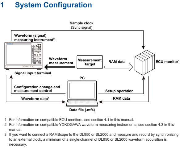
The ECU monitoring synchronization option (/EM1 or - EM1) is an extended function of the IS8000 integrated software, which can synchronize the waveform measured by waveform measuring instruments (such as DL950, SL2000) with the RAM data obtained by the ECU monitor (such as RAMScope) based on the sampling clock for display, supporting joint data analysis.
Core functions and system configuration
(1) Functional principles and core characteristics
Synchronization principle: The sampling clock generated by the waveform measuring instrument is used as a synchronization signal to be transmitted to the ECU monitor, and the measurement data of both parties is loaded through IS8000 software to achieve synchronous display of waveform and RAM data on the PC side.
Core functions:
|Functional Category | Specific Description|
|Synchronized display | ECU monitor RAM data and waveform measurement instrument waveform data are aligned and displayed based on sampling clock|
|Measurement Control | Supports measurement start/stop and recording of start/stop operations for ECU monitors and measuring instruments|
|Data Storage | Automatically merge RAM data with waveform data and save them as. mf4 format files; Support saving symbol definitions as XML files|
|Offline synchronization | Supports offline loading of saved waveform data (. wdf format) and RAM data (. mdf format), achieving timeline synchronization by aligning the "FirstData" points|
(2) System configuration requirements
Hardware compatibility:
ECU monitor: Supports RAMScope GT122, GT170EXG (RAM measurement module only), the latest compatible models need to refer to Yokogawa official website;
Waveform measuring instruments: Yokogawa DL950, SL2000 (require installation of input modules that match the measurement target);
PC communication interface: It needs to support USB (USBTMC, VISA protocol) or Ethernet (VXI-11, HiSLIP protocol), and a dedicated USB driver needs to be installed (which can be downloaded from) https://tmi.yokogawa.com/library/ Download).
PC system requirements: According to the usage scenario, it can be divided into two types of configurations, as follows:
|Usage scenario | CPU requirements | Memory requirements | SSD requirements | Operating system|
|10G Ethernet communication/trigger DAQ (up to 24 hours continuous recording) | Intel Core i7-10700K and above (4 cores, 8 threads, 4.7 GHz+) | 16 GB and above | 512 GB and above (NVMe SSD recommended, read/write speed 3 GB/s+) | Windows 10 64 bit Windows 11|
|1G Ethernet/USB communication/offline analysis | Intel Core i5-10210U and above (4 cores, 8 threads, 4.2 GHz+) | 8 GB and above | 256 GB and above (read/write speed of 400 MB/s+) | Windows 10 64 bit Windows 11|
Additional requirements: Screen resolution of 1366 × 768 or higher (100% zoom), mouse and printer (optional) are required.
Operation process: from configuration to data management
(1) Hardware connection and software configuration
Hardware connection steps:
Connect the measuring instrument to the ECU monitor: Connect the sampling clock output terminal (CLKO, with GND) of DL950/SL2000 to the synchronization signal input terminal of the ECU monitor;
Connect PC: The measuring instrument is connected to the PC via Ethernet or USB, and the ECU monitor is connected to the PC via USB;
Special note: If the ECU monitor is RAMScope, it is necessary to first configure RAM measurement related settings through RAMScope V/VP and verify the data acquisition function. Close the software before connecting to IS8000.
Software device registration and connection:
|Step | Operation Content|
|1 | Start the IS8000 software, click on "DAQ" to enter the device connection window|
|When connecting for the first time, click "Add", select the communication method (Ethernet/USB), and then click "Search" to search for the device|
|3 | Check the measurement instrument (such as DL950) and ECU monitor (such as RAMScope) in the search results, and click "Register" to complete the registration|
|4. Check the target device in the registered device list and click "Next" to enter the measurement and display settings window|
RAM data measurement channel settings:
Click "Add Channel" in the "Measurement Setting" window and import the symbol definition file (in. a2l format, generated by RAMScope VP) through "Edit>Import File", or manually enter the symbol, address, and data type;
After importing, click "Add" to add the RAM data channel to the channel list. After confirmation, click "Next" to enter DAQ settings.
Time reference synchronization setting:
Check 'Relative time' in the 'Time Base' section of the 'DAQ Setting' window (based on measuring instrument clock synchronization ECU monitor);
Configure the record saving path (default path: C: Users Username Documents YOKOGAWA IS8000), file name rules, etc. Click "OK" to complete the configuration and enter the DAQ control interface.
- OMRON
- ABB
- General Electric
- EMERSON
- Honeywell
- HIMA
- ALSTOM
- Rolls-Royce
- MOTOROLA
- Rockwell
- Siemens
- Woodward
- YOKOGAWA
- FOXBORO
- KOLLMORGEN
- MOOG
- KB
- YAMAHA
- BENDER
- TEKTRONIX
- Westinghouse
- AMAT
- AB
- XYCOM
- Yaskawa
- B&R
- Schneider
- KONGSBERG
- NI
- WATLOW
- ProSoft
- SEW
- ADVANCED
- Reliance
- TRICONEX
- METSO
- MAN
- Advantest
- STUDER
- DANAHER MOTION
- Bently
- Galil
- EATON
- MOLEX
- DEIF
- B&W
- ZYGO
- Aerotech
- DANFOSS
- Beijer
- Moxa
- Rexroth
- Johnson
- WAGO
- TOSHIBA
- BMCM
- SMC
- HITACHI
- HIRSCHMANN
- Application field
- XP POWER
- CTI
- TRICON
- STOBER
- Thinklogical
- Horner Automation
- Meggitt
- Fanuc
- Baldor
- SHINKAWA
- Other Brands
- UniOP
- KUKA
- Iba
- Beckhoff
-
 Basler ACA2000-50GM Interface Module
 -
 Basler AEC63-7 Analog Excitation Controller
 -
 Basler PRS 250 Veri-Sync Relay
 -
 Basler SR4A-2B15B3A Static Voltage Regulator
 -
Basler BE1-32R Power Relay
-
 Basler SR8A-2B06B3E Static Voltage Regulator
 -
 Basler BE1-81 O/U Frequency Relay
 -
 Basler BE1-51A-K2E-W6M-B1N0F Overcurrent Relay
 -
 Basler BE1-851 Overcurrent Relay G3A1S1 – 48-125V AC/DC
 -
 Basler BEI-51 Overcurrent Relay – NSN 5945-01-293-2363
 -
 Basler Electric L301KC Protective Relay – L301KC
 -
 Basler DECS-100-B15 Automatic Voltage Regulator – Generator AVR
 -
 Basler SR4A-2B15B3A Static Voltage Regulator – SR4A2B15B3A
 -
 Basler UF 312 Under Frequency Protective Module – 9094700100
 -
 Basler Electric MVC 232 Manual Control Module – 60VAC 55VDC 20A
 -
Basler PRS 250 Veri-Sync Relay – Generator Synchronizing Relay
-
 Basler DECS-100-A05 Digital Regulator Review
 -
 Basler AEM-2020 Analog Expansion Module Specs
 -
 Basler DECS-100-B15 Digital Excitation Specs
 -
 Basler Electric 9125600106 Regulator Component
 -
 Basler BE1-51A-K1E-W6M-B1N0F Overcurrent Relay
 -
 Basler MVC-301 MVC 300 Excitation Controller
 -
 Basler SSR 32-12 Static Voltage Regulator
 -
 Basler 9-2849-00-101 Control Module
 -
 Basler BE1-51A Overcurrent Relay
 -
 Basler BE1-51/27R Overcurrent Relay
 -
 Basler BE1-51 Overcurrent Relay
 -
 Basler SR8A-2B15B3A Static Voltage Regulator
 -
 Basler BE32965001 Transformer and Timer Board
 -
 Basler 9174700100 EL200-7 Excitation Limiter
 -
 Basler BE2000E AVR Voltage Regulator
 -
Basler BE1-87G Differential Relay
-
 Basler BE21834001 Generator Control Module
 -
Basler DECS-100-B15 AVR
-
 Basler D90 96801 100 PCB Card
 -
 Basler XR2002F Voltage Regulator (110 VAC, 48-480 Hz)
 -
 Basler SR8A-2B14B3A Regulator
 -
 Basler 9561500100 Module
 -
 Basler DECS-400 BE1-11 System
 -
 Basler DECS-100-B15 Excitation Control
 -
 Basler SCP 210 Frequency Controller
 -
Basler SR4A-2B15B3A Static Voltage Regulator
-
Basler BE1-32R Power Relay
-
 Basler PIA2400-17GM Power Interface Adapter
 -
 Basler MVC 232 Manual Voltage Control Module
 -
 Basler SSR 32-12 Static Voltage Regulator
 -
 Basler 5MW AVR Generator Voltage Regulator
 -
 Basler VR63-4B Voltage Regulator
 -
Basler DECS-100-A05 AVR for Engine Generator
-
Basler DECS-100-B15 Automatic Voltage Regulator
-
Basler BE1-32R Directional Power Relay
-
Basler BE1-87B Differential Relay
-
 Basler UFOV 260A Protective Module
 -
 Basler 9-2614-02-100 PCB Rev M
 -
Basler DECS-100-B15 Digital AVR
-
 Basler 9284900103 PS DECS-400N
 -
 Basler D4N3H1U Intertie Protection
 -
 Basler DECS-100-B15 A15 AVR
 -
 Basler KR4F Voltage Regulator
 -
 Basler BE26434 T14 Transformer
 -
 Basler SR8A-2B15B3A Regulator
 -
 Westinghouse 774B472A12 AR Relay
 -
Basler DECS-100-B15 AVR
-
Basler XR2002F Regulator 110V
-
Basler SR125-E Static Regulator
-
Basler SSR 125-12 Regulator
-
Basler MOC2599 Motor Pot
-
 Basler BE1-DFPR Feeder Relay
 -
 Basler CBS 305 Current Boost
 -
Basler BE1-25 AutoSync
-
Basler MVC 300 Voltage Control
-
 Basler BE3-25A AutoSync
 -
 Basler KR7FF Static Regulator
 -
Basler 90-49000-100 Regulator
-
 Basler 880 kVA Dry Type Transformer Specs
 -
Basler Electric BE1-25 Sync-Check Relay Specs
-
 Basler SSR 125-12 Voltage Regulator Specs
 -
 Basler Electric BE1-851 Overcurrent Relay Review
 -
Basler Electric 149D930G02 Control Sub-Assembly
-
 Basler Electric BE1-81O/UT Frequency Relay Specs
 -
 Basler Electric BE1-51/27C Overcurrent Relay
 -
 Basler Electric 149D956G02 Industrial Component
 -
Basler Electric BE1-51A Overcurrent Relay Specs
-
 Basler Electric BE1-40Q Loss of Excitation Relay
 -
 Basler DECS-200 Excitation Control System
 -
 Basler DECS-200 Voltage Regulator 56-277V AC / 125V DC
 -
Basler BE1-87T Transformer Differential Relay
-
 Basler RDP-110-S1 Protection Relay
 -
 Basler BE1-700V Digital Protective Relay
 -
 Basler BE1-951 Overcurrent Protection System
 -
 Basler DECS-300 Digital Excitation Control
 -
 Basler DECS-200 Digital Excitation Control
 -
 Basler DECS-200-1C Excitation Control System
 -
Basler DECS-200-1L Digital Excitation Control
-
 Basler Electric BE1-GPS Generator Protection System
 -
Basler Electric DECS-200-1C Digital Excitation Controller
-
 Basler Electric DECS125-15 Excitation Control with Power Module
 -
Basler Electric BE1-87G Differential Relay
-
 Basler Electric BE1-11 Protection System I5A3M2P2N0EA00
 -
Basler Electric DECS-200-1C Excitation Control System
-
Basler Electric BE1-11g Generator Protection Relay
-
Basler Electric DECS 125-15-B2C1 V2.0.9 Excitation Control
-
 Basler Electric BE1-81O/UT3ED1JA7N2F Frequency Relay
 -
Basler Electric BE1-81O/UT3EE1YB7N1F Frequency Relay
-
 Basler Electric DECS-200-1L Digital Excitation Control System
 -
Basler DECS125-15-B2C1 Excitation Control
-
 Basler 9507900205 SSR Retrofit Voltage Regulator
 -
 Basler BE2000E Digital Voltage Regulator
 -
 Basler BE1-GPS Generator Protection System
 -
Basler DECS-250-CN1CN1N Digital Excitation Control
-
 Basler DGC-2020 Genset Controller
 -
Basler BE1-81O UT3ED1LA7N0F Frequency Relay (Variant)
-
 Basler BE1-81O UT3EE1YA9S0F Frequency Relay (Variant)
 -
Basler BE1-81O Over/Under Frequency Relay
-
Basler DECS125-15 Digital Excitation Control
-
Basler Electric BE1-951 Overcurrent Protection System
-
 Basler Electric BE1-700V Digital Protective Relay
 -
 Basler Electric APR63-5 Automatic Voltage Regulator
 -
Basler Electric BE1-851 Overcurrent Protection System
-
Basler Electric DECS-250-LN1SN1N Excitation Control
-
 Basler Electric BE1-87T Transformer Differential Relay
 -
Basler Electric DECS-200-1L Excitation Control System
-
 Basler Electric 9310300100 DECS-300 Excitation Control
 -
 Basler Electric SSE-N 125-4.5KW Shunt Exciter Regulator
 -
 Basler Electric DGC-2020HD-5NS1DNSBA Genset Controller
 -
Basler Electric BE1-81-O/UT3EE1JB7N1F Frequency Relay
-
Basler Electric BE1-81T1EE1WA0N1F Frequency Relay
-
 Basler Electric BE1-25M1EA6PN5R1F Sync-Check Relay


