
DEIF PPU-3 Parallel and Protection Unit
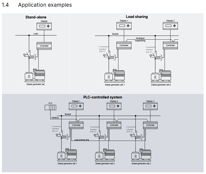
Stand alone operation: independent power supply control for a single generator;
Parallel with other generators: Multiple generators are synchronized in parallel to achieve load distribution and coordinated control.
Its core value lies in simplifying the generator control chain, which can be connected to the PLC control system through digital/analog I/O or serial communication, and has flexible functional expansion capabilities.
DEIF PPU-3 Parallel and Protection Unit
Product basic positioning and core applications
PPU-3 is a compact microprocessor control unit launched by DEIF, which integrates the protection and control functions of synchronous/asynchronous generators in an "integrated" design. It has a built-in galvanized separated three-phase measurement circuit and is designed for ship application scenarios. It supports two core working modes (which can be combined):
Stand alone operation: independent power supply control for a single generator;
Parallel with other generators: Multiple generators are synchronized in parallel to achieve load distribution and coordinated control.
Its core value lies in simplifying the generator control chain, which can be connected to the PLC control system through digital/analog I/O or serial communication, and has flexible functional expansion capabilities.
Core functional modules
(1) Display and operation unit
Display configuration: The display unit (DU-2) is independently designed and can be directly installed on the host or at the front end of the distribution cabinet door (with a standard 3m display cable). A single PPU-3 can expand up to 2 additional display units (up to 200m away);
Display content: Real time display of all measured values, calculated values, alarm information, and event logs;
Extended operation panel: Optional AOP-1 (16 configurable LEDs+8 configurable buttons) or AOP-2 (16 configurable LEDs+8 configurable buttons+1 status relay), supporting CAN bus communication.
(2) Regulation Modes
According to the control object (governor/automatic voltage regulator), provide multiple types of switchable standard regulation modes to meet different operational requirements:
Specific functions of control object adjustment mode
Governor maintains a fixed frequency to maintain stable generator output frequency
Fixed power (base load) setting for fixed active power output
Frequency droop automatically adjusts the frequency as the load changes, adapting to parallel load distribution
Load sharing: Balanced allocation of active loads when multiple machines are connected in parallel
Automatic voltage regulator (AVR, optional option D1) with fixed voltage to maintain stable generator output voltage
Fixed reactive power setting for fixed reactive power output
Fixed power factor maintains power factor stability
Reactive load sharing: Balanced allocation of reactive load when multiple machines are connected in parallel
Voltage droop automatically adjusts voltage with changes in reactive load, suitable for parallel scenarios
(3) Self checking and configuration tools
Self test: Perform periodic self tests at startup, display fault information in plain text on the screen, and trigger alarms through relay outputs (status outputs);
M-Logic (Micro PLC): Free integration into PC tool software, supports custom input/output functions and logic conditions, and adapts to personalized application scenarios;
Configuration method:
Local: configured through the password protection menu of the display unit;
Remote: Connect to a PC via USB and use the free Windows version PC tool software (available from the DEIF download center), which supports parameter monitoring, configuration saving/downloading, and firmware updates.
(4) Engine control and protection (optional function)
After installing the engine control and protection module, the PPU-3 can achieve:
Engine start stop sequence control;
Engine protection function: Provides a complete backup of the engine shutdown channel in case of main processor failure, ensuring equipment safety.
(5) CANshare function (optional G9 option)
CANshare provides:
Digital load distribution and line fault (disconnection, short circuit) monitoring;
Support position feedback and monitoring of up to 4 bus circuit breakers (BTBs);
Manage up to 5 load distribution segments;
Monitoring of active/reactive load distribution;
Dead bus closing and first startup discrimination;
Simulation testing mode before debugging.
Standard protection functions (Protections)
PPU-3 is equipped with multiple protection functions that comply with IEEE Std. C37.2-1996 (R2001) standards, covering core fault scenarios of generators and busbars. Some functions support multiple threshold settings:
Protection Function ANSI Number Threshold Order Core Function
Generator reverse power (32) 2nd order to prevent the generator from absorbing grid power (such as when the turbine loses steam)
Generator over current (50/51) 6th order protection of the generator from overload current damage
Voltage dependent overcurrent (51V) 1st order combined with voltage state to determine overcurrent and avoid false triggering
Inverse time over current (51) The larger the first-order current, the shorter the action time, making it suitable for different overload scenarios
Generator over/under voltage (59)/(27) 2nd/3rd order protection for generator insulation and load from overvoltage/undervoltage impact
Generator over/under frequency (81) 3rd/3rd order to prevent frequency deviation caused by abnormal generator speed
Busbar over/undervoltage (59)/(27) 3rd/4th order protection for busbars and downstream loads from overvoltage/undervoltage damage
Busbar over/under frequency (81) 3rd/4th order to maintain bus frequency stability
Busbar voltage imbalance (60) 1st order prevention of equipment failure caused by three-phase voltage imbalance
Generator overload (32) 5th order to avoid long-term operation of the generator beyond rated load
Current/Voltage Imbalance (60) 1st order protection for generators and loads from damage caused by unbalanced current/voltage
Overexcitation/Loss of excitation (40/32 RV) 1st order protection generator excitation system to avoid magnetic field anomalies
Hardware and interface specifications
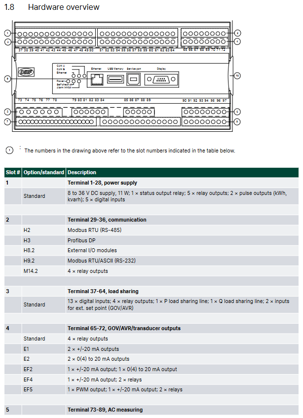
(1) Hardware architecture and slot allocation
The PPU-3 adopts a "slot based" hardware design, with fixed slots corresponding to different functional modules. Each slot only supports one hardware option, and the core slot functions are as follows:
Slot Number Function Category Standard Configuration/Optional Options Core Interface and Parameters
1. Power supply and basic I/O standard 8-36V DC power supply (11W); 1 status output relay; 5 relay outputs; 2 pulse outputs (kWh, kvarh); 5 digit inputs
Communication options include H2 (Modbus RTU/ASCII, RS-485), H3 (Profibus DP), etc., which are responsible for serial communication with external systems such as PLCs
3 load distribution standards with 13 numerical inputs; 4 relay outputs; 1 P (active) load distribution line; 1 Q (reactive power) load distribution line; 2 external set point inputs (GOV/AVR)
4 GOV/AVR/transmitter output standards (4 relay outputs); Optional E1 (2-channel+/-25mA), E2 (2-channel 0 (4) -20mA) and other output control signals can be sent to the speed regulator/AVR, or used as transmitter signal output
5 AC measurement standards, 3 generator voltage inputs; 3-channel generator current input; 3-channel bus/grid voltage input
6 Analog Output Expansion Optional F1 (2-channel 0 (4) -20mA transmitter output) to expand analog output channels
7 engine control and I/O expansion options include M4 (engine control, digital/analog I/O) and H7 (software level engine communication) to achieve engine start stop control, I/O expansion, and specific engine protocol docking
8. Advanced communication and load distribution options include G9 (CANshare), H5 (specific engine protocols such as Caterpillar, MTU), digital load distribution, and engine specific communication protocol docking
9 Ethernet communication options include N (Ethernet TCP/IP, supporting Modbus TCP/IP, EtherNet/IP, SMS/email alarms) to achieve remote monitoring and alarm notification over Ethernet
(2) Key technical parameters
Parameter category specific specifications
Working environment temperature: -25~70 ° C (-25~60 ° C with N option; UL/cUL certified environment maximum 55 ° C); Humidity: 97% RH (IEC 60068-2-30); Altitude: 0-4000m (downgraded for use from 2001 to 4000m)
Measurement range voltage: 100~690V AC (± 20%, UL/cUL certified maximum 600V AC); Current: 1/5A AC (from CT); Frequency: 30~70Hz
Auxiliary power terminal 1-2:12/24V DC nominal (8-36V DC operation, maximum 11W); Terminal 98-99:12/24V DC nominal (8-36V DC operation, maximum 5W); 2A slow melting fuse protection is required
Input/output digital input: optocoupler isolation, 8-36V DC conduction (impedance 4.7k Ω); Analog input: 0 (4) -20mA (impedance 50 Ω) RPM(MPU:2-70V AC,10-10000Hz); Relay output: 250V AC/30V DC (5A, UL/cUL certified 2A resistive load); Analog output: 0 (4) -20mA/± 25mA (isolated, maximum load 500 Ω)
Electrically isolated AC voltage from other I/O: 3250V AC (50Hz, 1min); AC current and other I/O: 2200V AC (50Hz, 1min); Analog output and other I/O: 550V AC (50Hz, 1min)
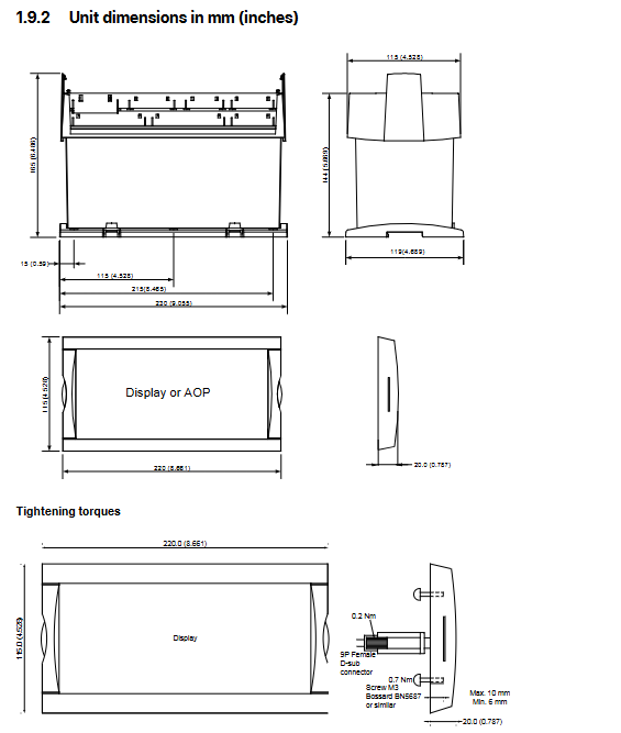
Protection level host: IP20; Display unit: IP40 (optional L gasket can be upgraded to IP54, required for RS certification applications)
Certified ship certification: certified by all mainstream classification societies; Safety certification: EN 61010-1, UL 508, CSA 22.2 No.14-05; EMC certification: EN 61000-6-2/4, IEC 60255-26
Optional Features and Accessories
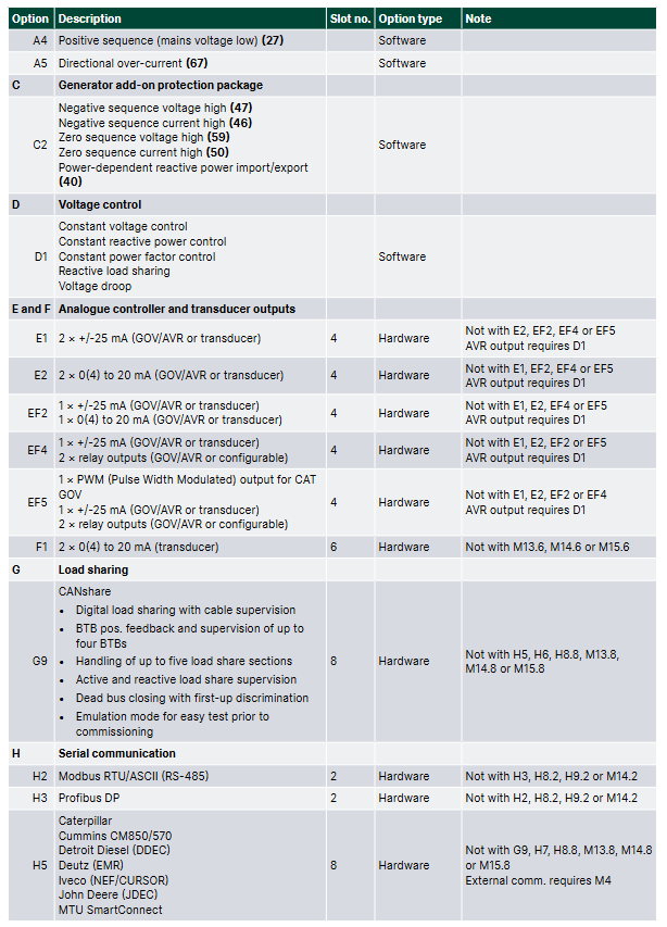
(1) Core optional options (some key options)
Specific description of option code function category
A-series power grid protection package A1 (limited time undervoltage 27t, undervoltage+low reactive power 27Q, etc.), A5 (directional overcurrent 67)
C2 Generator Extended Protection Package Negative Sequence Voltage High 47, Negative Sequence Current High 46, Zero Sequence Voltage High 59, etc
D1 Voltage Control Fixed Voltage, Fixed Reactive Power, Fixed Power Factor, Reactive Load Distribution, Voltage Drop
G9 CANshare digital load distribution+line monitoring, multi BTB monitoring, dead bus closing
H2/H3 serial communication H2 (Modbus RTU/ASCII, RS-485), H3 (Profibus DP)
N Ethernet Modbus TCP/IP, EtherNet/IP, SMS/email alerts
Y1/Y11 display and control Y1 (engine and GB control), Y11 (display unit without local control button)
(2) Standard and optional accessories
Accessory type, specific product usage, model/remarks
Display Unit DU-2 (Standard): The host is equipped with Display 2912210050, and the display layout needs to be specified
DU-2 (extension) additional extension display 2912890030, supports CAN bus
AOP-1 expansion operation buttons and LED 2912890040 on the operation panel, with a maximum of one unit per display
AOP-2 expansion panel with status relay 2912890050, up to 5 units per PPU-3
Cable display cable (3m/6m/1m) connects the display unit to the host 1022040076 (3m), 1022040057 (6m), etc
USB cable (3m) PC configuration connection 1022040065
Cross Ethernet cable (3m) N option Ethernet connection 1022040055
IP54 display gasket (L) enhances the protection level of the display unit 1134510010, required for RS certification
Ordering and Disclaimer
(1) Order specifications
Required information: model (such as PPU-3 Marine), variant number (such as 01 with display/07 without display), product number (such as 2912210030-01);
Optional information: Please specify the selected functional options (such as M4, Y1, H2) and accessories (such as AOP-2, IP54 gasket);
Example: Product number 2912210030-01 (PPU-3 Marine 01 with display)+option M4 (engine control)+Y1 (engine and GB control)+H2 (Modbus RTU).
(2) Disclaimer
DEIF reserves the right to modify document content without prior notice;
The English version of the document is the latest authoritative version, and there may be delays in the translated version. In case of any conflicts, the English version shall prevail;
DEIF is not responsible for the accuracy of the translated version.
- OMRON
- ABB
- General Electric
- EMERSON
- Honeywell
- HIMA
- ALSTOM
- Rolls-Royce
- MOTOROLA
- Rockwell
- Siemens
- Woodward
- YOKOGAWA
- FOXBORO
- KOLLMORGEN
- MOOG
- KB
- YAMAHA
- BENDER
- TEKTRONIX
- Westinghouse
- AMAT
- AB
- XYCOM
- Yaskawa
- B&R
- Schneider
- KONGSBERG
- NI
- WATLOW
- ProSoft
- SEW
- ADVANCED
- Reliance
- TRICONEX
- METSO
- MAN
- Advantest
- STUDER
- DANAHER MOTION
- Bently
- Galil
- EATON
- MOLEX
- DEIF
- B&W
- ZYGO
- Aerotech
- DANFOSS
- Beijer
- Moxa
- Rexroth
- Johnson
- WAGO
- TOSHIBA
- BMCM
- SMC
- HITACHI
- HIRSCHMANN
- Application field
- XP POWER
- CTI
- TRICON
- STOBER
- Thinklogical
- Horner Automation
- Meggitt
- Fanuc
- Baldor
- SHINKAWA
- Other Brands
- UniOP
- KUKA
- Iba
- Beckhoff
-
 Basler DECS-200-2L Digital Excitation Control
 -
 Basler BE1-47N Voltage Phase Sequence Relay
 -
 Basler AEC63-7 Analog Excitation Controller 220-277V
 -
 Basler BE1-50/51B-107 Overcurrent Relay
 -
 Basler Electric BE1‑32R BE1‑E1P‑BON0F Protective Relay
 -
 Basler BE1-25 Solid State Time Overcurrent Relay M1EA6PA5S1F
 -
 Basler MVC 232 Manual Voltage Control Module 90 37000 103 60VAC 55VDC
 -
 Basler RAL6144-16GM Racer GigE Line Scan Camera
 -
 Basler SSR 63-12 Static Voltage Regulator
 -
 Basler BE1-51A Overcurrent Relay
 -
 Basler BE1-87T Solid State Protective Relay
 -
 Basler SR4A2B01B3A Static Voltage Regulator
 -
 Basler SSR 32-12 Static Voltage Regulator
 -
 Basler TRR00696 Transformer 1KVA 115V
 -
 Basler DECS-100-B15 AVR Replacement
 -
Basler BE1-27 Under-Voltage Relay
-
 Basler ACA2000-50GM Interface Module
 -
 Basler AEC63-7 Analog Excitation Controller
 -
 Basler PRS 250 Veri-Sync Relay
 -
 Basler SR4A-2B15B3A Static Voltage Regulator
 -
Basler BE1-32R Power Relay
-
Basler SR8A-2B06B3E Static Voltage Regulator
-
Basler BE1-81 O/U Frequency Relay
-
 Basler BE1-51A-K2E-W6M-B1N0F Overcurrent Relay
 -
Basler BE1-851 Overcurrent Relay G3A1S1 – 48-125V AC/DC
-
 Basler BEI-51 Overcurrent Relay – NSN 5945-01-293-2363
 -
Basler Electric L301KC Protective Relay – L301KC
-
 Basler DECS-100-B15 Automatic Voltage Regulator – Generator AVR
 -
 Basler SR4A-2B15B3A Static Voltage Regulator – SR4A2B15B3A
 -
 Basler UF 312 Under Frequency Protective Module – 9094700100
 -
Basler Electric MVC 232 Manual Control Module – 60VAC 55VDC 20A
-
Basler PRS 250 Veri-Sync Relay – Generator Synchronizing Relay
-
 Basler DECS-100-A05 Digital Regulator Review
 -
 Basler AEM-2020 Analog Expansion Module Specs
 -
 Basler DECS-100-B15 Digital Excitation Specs
 -
Basler Electric 9125600106 Regulator Component
-
Basler BE1-51A-K1E-W6M-B1N0F Overcurrent Relay
-
 Basler MVC-301 MVC 300 Excitation Controller
 -
 Basler SSR 32-12 Static Voltage Regulator
 -
 Basler 9-2849-00-101 Control Module
 -
Basler BE1-51A Overcurrent Relay
-
 Basler BE1-51/27R Overcurrent Relay
 -
 Basler BE1-51 Overcurrent Relay
 -
 Basler SR8A-2B15B3A Static Voltage Regulator
 -
 Basler BE32965001 Transformer and Timer Board
 -
 Basler 9174700100 EL200-7 Excitation Limiter
 -
 Basler BE2000E AVR Voltage Regulator
 -
Basler BE1-87G Differential Relay
-
 Basler BE21834001 Generator Control Module
 -
Basler DECS-100-B15 AVR
-
 Basler D90 96801 100 PCB Card
 -
 Basler XR2002F Voltage Regulator (110 VAC, 48-480 Hz)
 -
 Basler SR8A-2B14B3A Regulator
 -
 Basler 9561500100 Module
 -
 Basler DECS-400 BE1-11 System
 -
 Basler DECS-100-B15 Excitation Control
 -
 Basler SCP 210 Frequency Controller
 -
Basler SR4A-2B15B3A Static Voltage Regulator
-
Basler BE1-32R Power Relay
-
 Basler PIA2400-17GM Power Interface Adapter
 -
 Basler MVC 232 Manual Voltage Control Module
 -
 Basler SSR 32-12 Static Voltage Regulator
 -
Basler 5MW AVR Generator Voltage Regulator
-
 Basler VR63-4B Voltage Regulator
 -
Basler DECS-100-A05 AVR for Engine Generator
-
Basler DECS-100-B15 Automatic Voltage Regulator
-
Basler BE1-32R Directional Power Relay
-
Basler BE1-87B Differential Relay
-
 Basler UFOV 260A Protective Module
 -
 Basler 9-2614-02-100 PCB Rev M
 -
Basler DECS-100-B15 Digital AVR
-
 Basler 9284900103 PS DECS-400N
 -
 Basler D4N3H1U Intertie Protection
 -
 Basler DECS-100-B15 A15 AVR
 -
 Basler KR4F Voltage Regulator
 -
 Basler BE26434 T14 Transformer
 -
 Basler SR8A-2B15B3A Regulator
 -
 Westinghouse 774B472A12 AR Relay
 -
Basler DECS-100-B15 AVR
-
Basler XR2002F Regulator 110V
-
Basler SR125-E Static Regulator
-
Basler SSR 125-12 Regulator
-
Basler MOC2599 Motor Pot
-
 Basler BE1-DFPR Feeder Relay
 -
 Basler CBS 305 Current Boost
 -
Basler BE1-25 AutoSync
-
Basler MVC 300 Voltage Control
-
 Basler BE3-25A AutoSync
 -
 Basler KR7FF Static Regulator
 -
Basler 90-49000-100 Regulator
-
 Basler 880 kVA Dry Type Transformer Specs
 -
Basler Electric BE1-25 Sync-Check Relay Specs
-
 Basler SSR 125-12 Voltage Regulator Specs
 -
 Basler Electric BE1-851 Overcurrent Relay Review
 -
Basler Electric 149D930G02 Control Sub-Assembly
-
 Basler Electric BE1-81O/UT Frequency Relay Specs
 -
 Basler Electric BE1-51/27C Overcurrent Relay
 -
 Basler Electric 149D956G02 Industrial Component
 -
Basler Electric BE1-51A Overcurrent Relay Specs
-
 Basler Electric BE1-40Q Loss of Excitation Relay
 -
Basler DECS-200 Excitation Control System
-
 Basler DECS-200 Voltage Regulator 56-277V AC / 125V DC
 -
Basler BE1-87T Transformer Differential Relay
-
 Basler RDP-110-S1 Protection Relay
 -
 Basler BE1-700V Digital Protective Relay
 -
 Basler BE1-951 Overcurrent Protection System
 -
 Basler DECS-300 Digital Excitation Control
 -
 Basler DECS-200 Digital Excitation Control
 -
 Basler DECS-200-1C Excitation Control System
 -
Basler DECS-200-1L Digital Excitation Control
-
 Basler Electric BE1-GPS Generator Protection System
 -
Basler Electric DECS-200-1C Digital Excitation Controller
-
 Basler Electric DECS125-15 Excitation Control with Power Module
 -
Basler Electric BE1-87G Differential Relay
-
 Basler Electric BE1-11 Protection System I5A3M2P2N0EA00
 -
Basler Electric DECS-200-1C Excitation Control System
-
Basler Electric BE1-11g Generator Protection Relay
-
Basler Electric DECS 125-15-B2C1 V2.0.9 Excitation Control
-
Basler Electric BE1-81O/UT3ED1JA7N2F Frequency Relay
-
Basler Electric BE1-81O/UT3EE1YB7N1F Frequency Relay
-
 Basler Electric DECS-200-1L Digital Excitation Control System
 -
Basler DECS125-15-B2C1 Excitation Control
-
 Basler 9507900205 SSR Retrofit Voltage Regulator
 -
 Basler BE2000E Digital Voltage Regulator
 -
 Basler BE1-GPS Generator Protection System
 -
Basler DECS-250-CN1CN1N Digital Excitation Control
-
 Basler DGC-2020 Genset Controller
 -
Basler BE1-81O UT3ED1LA7N0F Frequency Relay (Variant)


