
Toshiba TOSBERT S7 series frequency converter
Core objective: To ensure the safety and proper use of frequency converters by users, fully leveraging their advantages of vector control, high efficiency, energy saving, and multi scenario adaptation, while reducing the incidence of failures and maintenance costs.
Toshiba TOSBERT S7 series frequency converter
Document Overview and Equipment Core Positioning
1. Document positioning and target audience
Document attribute: Toshiba TOSBERT S7 series inverter official complete version user manual, covering the entire process from basic installation to advanced function configuration and fault maintenance. It is the core operation guide for electrical engineers, equipment operation and maintenance personnel, and installation and debugging personnel.
Core objective: To ensure the safety and proper use of frequency converters by users, fully leveraging their advantages of vector control, high efficiency, energy saving, and multi scenario adaptation, while reducing the incidence of failures and maintenance costs.
2. Basic equipment information
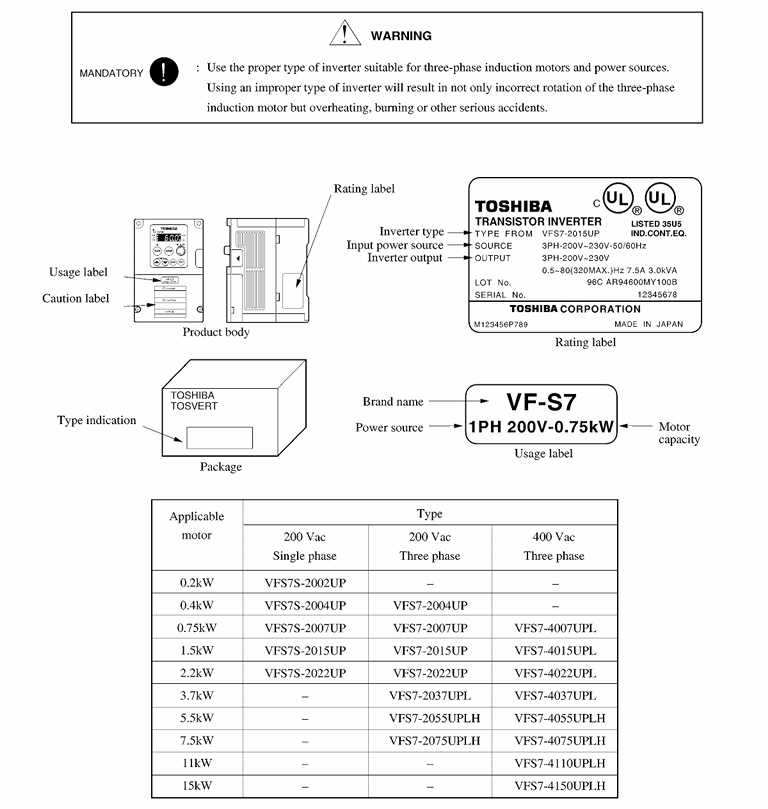
(1) Full range specifications of models
The TOSBERT S7 series covers the full power range from low voltage to high voltage, suitable for different industrial scenarios. The specific classifications are as follows:
Voltage level, power range, model identification, core application, typical models
200V level (single-phase/three-phase) 0.4-75kW S7-2XXX small conveyor, packaging machine, laboratory equipment S7-2037H (37kW, three-phase input), S7-2004S (0.4kW, single-phase input)
400V level (three-phase) 0.75-630kW S7-4XXX fan, pump, compressor, machine tool, crane S7-4220H(220kW)、S7-4007S(0.75kW)、S7-4630H(630kW)
High voltage level (6.6kV/11kV) 200-2000kW S7-HVXXX large fan, high-pressure compressor, industrial pump set S7-HV630(6.6kV/630kW)、S7-HV1100(11kV/1100kW)
(2) Analysis of Model Coding Rules
Taking the typical model "S7-4220H-F" as an example, the meanings of each paragraph are as follows:
S7: Product series identification (TOSBERT S7 series);
4: Voltage level (2=200V level, 4=400V level, HV=high voltage level);
220: Rated capacity (220kW, high voltage level directly labeled power, such as HV630=630kW);
H: Basic configuration (H=standard configuration, S=simple configuration, L=low-noise configuration);
F: Optional functions (F=built-in braking unit, C=built-in communication module, P=with input reactor).
(3) Core technological advantages
Leading control accuracy: In sensorless vector control (SVC) mode, it can output 150% rated torque at 0.5Hz with a speed accuracy of ± 0.1%; Under the sensor vector control (FVC) mode, the speed accuracy can reach ± 0.01%, which is suitable for high-precision speed control scenarios such as machine tools and printing machines.
Multi mode compatibility: Supports three core modes: V/f control, SVC, FVC, which can be switched with one click through parameters to adapt to different load types such as fans/pumps (variable torque), conveyors (constant torque), cranes (high torque start), etc.
Outstanding energy-saving performance: Built in fan/pump specific energy-saving curve, saving 5-15% energy compared to ordinary frequency converters; The automatic energy-saving mode can dynamically adjust the output voltage according to the load current, and the energy-saving effect is more significant under light load.
Protection and stability: The basic model has a protection level of IP20 (anti finger touch), with an optional IP40 (anti solid foreign object intrusion, anti splash water); The core power module adopts Toshiba's original IGBT, with a temperature resistance range of -10~50 ℃ and an MTBF (mean time between failures) of over 100000 hours.
Installation specifications and environmental requirements
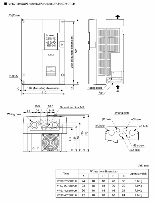
1. Installation method and space requirements
(1) Installation method (segmented by power)
Wall mounted installation: 200V level (≤ 75kW), 400V level (≤ 75kW), need to be fixed on a metal backplate with a thickness of ≥ 2mm, and the backplate needs to be grounded (grounding resistance ≤ 10 Ω); The flatness error of the installation surface should be ≤ 0.5mm to avoid vibration transmission.
Ground installation: 400V level (≥ 90kW), high voltage level, requiring a dedicated steel base with a height of ≥ 10cm (to prevent water damage and facilitate heat dissipation); A shock-absorbing pad (hardness 50-60 Shore hardness) should be added between the base and the ground to reduce equipment vibration during operation.
Parallel installation: When multiple frequency converters are parallel, the spacing should be ≥ 15cm (≤ 75kW) and ≥ 20cm (≥ 90kW), and it is forbidden to stack them up and down (which may cause poor heat dissipation of the upper equipment).
(2) Ventilation gap and heat dissipation requirements
The heat dissipation effect of the frequency converter directly affects its service life, and strict ventilation gaps are required for different power ranges:
Power Range Top Gap Bottom Gap Left and Right Side Gap Back Gap Heat Dissipation Method
≤ 75kW ≥ 10cm ≥ 10cm ≥ 5cm ≥ 10cm Natural heat dissipation+built-in fan
90-220kW ≥ 15cm ≥ 15cm ≥ 10cm ≥ 15cm Forced air cooling (dual fan redundant design)
≥ 250kW ≥ 20cm ≥ 20cm ≥ 15cm ≥ 20cm Forced air cooling+optional water cooling for heat dissipation
Special requirement: It is prohibited to install obstructions such as air ducts and cable trays above the frequency converter; The air outlet of the cooling fan should face the open area to avoid hot air backflow.
2. Environmental conditions limitations
Temperature: Operating environment temperature -10 ℃~40 ℃ (up to 50 ℃ for models without casing); Storage temperature -20 ℃~60 ℃; When the temperature exceeds 40 ℃, for every 1 ℃ increase, the rated output power decreases by 1% (up to a maximum of 50 ℃).
Humidity: Relative humidity ≤ 90% RH, no condensation (dehumidification devices or anti condensation heaters need to be installed in condensation environments); Avoid using in high humidity, foggy, and salt spray environments (anti-corrosion models should be selected for special environments).
Altitude: ≤ 1000m (for every 100m increase in altitude, atmospheric pressure decreases by approximately 1kPa); When it exceeds 1000m, the rated power usage needs to be reduced (such as 5% reduction at 1500m and 20% reduction at 3000m).
Vibration: During operation, the vibration acceleration is ≤ 0.6G (10-50Hz), and the amplitude is ≤ 0.08mm (50-150Hz); Exceeding the range requires the installation of a vibration reduction base, otherwise it may cause loose terminals and damage to capacitors.
Other: No flammable or explosive gases, no corrosive gases, no large amount of dust (IP40+dust cover should be selected for dusty environments); Stay away from strong electromagnetic interference sources (such as welding machines and high-voltage transformers), with a distance of ≥ 2m.
3. Transportation and storage precautions
Transportation: it shall be fixed in the special packing box during transportation, and the packing box shall be filled with cushioning materials (foam, pearl cotton); Do not invert or flip over to avoid severe collisions (which may cause damage to internal IGBT modules and capacitors); Transportation temperature -20 ℃~60 ℃, avoid direct sunlight exposure.
Storage: Long term storage (≥ 6 months) must meet the following requirements: temperature -20 ℃~40 ℃, humidity ≤ 60% RH; power on once a month (no load, voltage gradually increases from 0 to rated value for 30 minutes), activate the capacitor, and prevent electrolyte aging; Cover with a dust cover during storage to prevent dust from entering the ventilation openings.
Wiring specifications and hardware configuration
1. Main circuit wiring (detailed explanation by power segment)
The wiring of the main circuit directly affects the safe operation of the frequency converter, and there are significant differences in the configuration of terminals in different power ranges. It is necessary to strictly follow the instructions for operation:
(1) 200V level (0.4-75kW) main circuit terminal
Terminal identification function wiring requirements cable specifications (copper core)
Three phase power inputs of R/L1, S/L2, and T/L3 (single-phase models only connect R/L1 and S/L2) require a series circuit breaker (MCCB) with a capacity of 1.2-1.5 times the rated current of the frequency converter; Prohibit connecting power factor compensation capacitors 0.4-1.5kW: 1.5mm ²; 2.2-7.5kW:2.5mm²; 11-75kW:4-16mm²
U. The output of the V and W three-phase motors corresponds to the U, V, and W terminals of the motor, and the forward and reverse rotation of the motor can exchange any two phases; The cable length is ≤ 50m (thicker cables or additional output reactors are required if exceeding), consistent with the specifications of the input cable
PE protection grounding meets Class 3 grounding requirements, with a grounding resistance of ≤ 10 Ω; The grounding wire should be independent of the power grounding, and it is forbidden to share the same wire diameter with the neutral wire. The wire diameter should be ≥ 1/2 of the input cable diameter, and the minimum should not be less than 2.5mm ²
B1 and B2 brake resistors/brake unit connection power ≤ 15kW can be connected to built-in brake resistors; Power greater than 15kW requires an external braking unit to be selected according to the braking power, ≥ 2.5mm ²
(2) 400V level (0.75-630kW) main circuit terminal
Power ≤ 37kW: The terminal configuration is similar to that of 200V level, with the addition of "input reactor terminals (L1R, L2S, L3T)", which can be optionally equipped with input reactors to suppress harmonics.
Power ≥ 45kW: The terminals are divided into "main power input (L1, L2, L3)" and "output (U1, V1, W1)", and some models support dual power input (redundant design); The brake terminals are divided into "B1, B2 (main brake)" and "B3, B4 (auxiliary brake)", suitable for high-power braking requirements.
(3) High voltage level (6.6kV/11kV) main circuit terminal
Using high-voltage dedicated terminals (ceramic insulation material), divided into "high-voltage input (U, V, W)", "high-voltage output (u, V, W)", "grounding (PE)", "lightning arrester interface (LA, LB, LC)";
It is necessary to connect high-voltage lightning arresters and high-voltage reactors externally, and the wiring must be operated by high-voltage electricians, strictly following high-voltage safety regulations (such as measuring insulation resistance ≥ 1000M Ω after wiring).
2. Control circuit wiring (anti-interference+functional adaptation)
The wiring of the control circuit should balance functional implementation and anti-interference to avoid signal distortion that may cause the frequency converter to malfunction
(1) Analog input terminals (AI1, AI2)
Terminal default function configurable function wiring requirements anti-interference measures
AI1 0-10VDC frequency command 4-20mA current command (parameter P07.01 setting) 0-10V: input impedance 30k Ω, cable length ≤ 10m; 4-20mA: load resistance ≤ 500 Ω, cable length ≤ 20m, use shielded twisted pair with single end grounding of shielding layer (frequency converter side); The distance from the main circuit cable is ≥ 20cm, and parallel wiring is prohibited
AI2 4-20mA torque command 0-10VDC auxiliary command (parameter P07.02 setting) same as AI1
(2) Switching input terminals (DI1-DI8)
There are a total of 8 switch inputs, and the default functions are as follows:
DI1=Forward Rotation (FWD), DI2=Reverse Rotation (REV), DI3=Multi Speed 1 (S1), DI4=Multi Speed 2 (S2), DI5=Jog, DI6=Reset, DI7=Emergency Stop, DI8=Enable;
Wiring requirements: Input mode supports leakage/source switching (parameter P06.01), voltage 24Vdc ± 10%, current ≤ 10mA; cable uses 0.5-1.0mm ² shielded twisted pair, length ≤ 50m.
(3) Switching output terminals (DO1-DO4)
4-channel open collector output, capacity 250Vac/0.5A, 30Vdc/1A, default function:
DO1=RUN, DO2=FREQ REACH, DO3=ALARM, DO4=BRAKE;
Wiring requirements: An external load resistor (such as a relay coil) is required to avoid short circuits; Separate the wiring of cables and control input cables.
(4) Communication interface wiring
Standard RS485 interface: terminals TX+, TX -, RX+, RX -, supporting MODBUS-RTU protocol, baud rate 9600-115200bps (parameter P20.01), 8-bit data bits, optional checksum (none/odd/even);
Optional communication modules: PROFINET (P21 parameter group), EtherNet/IP (P22 parameter group), DeviceNet (P23 parameter group), require separate wiring and configuration of corresponding parameters;
Wiring requirements: RS485 cables should be shielded twisted pair, with a length of ≤ 1200m (9600bps), and the terminal should be connected to a 120 Ω matching resistor; The shielding layer is grounded at one end to avoid interference from grounding currents.
3. Grounding and lightning protection wiring specifications
Grounding requirements:
Protective grounding (PE terminal): Class 3 grounding is used, with a grounding resistance of ≤ 10 Ω (high voltage level ≤ 4 Ω); The grounding wire requires a yellow green dual color copper core wire with a wire diameter of ≥ 2.5mm ² (for high-power models, ≥ 4mm ²);
Signal grounding: The control circuit signal grounding (SG terminal) needs to be separated from the protective grounding and finally connected at one point (multi-point grounding is prohibited) to reduce interference.
Lightning protection wiring:
Outdoor installation or lightning prone areas require the installation of lightning arresters on the power input side (recommended model: Toshiba FV-200/400);
High voltage models require the installation of zinc oxide lightning arresters on the high-voltage input side to prevent lightning overvoltage from damaging the power module.
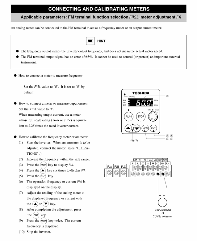
Operation panel and basic operation process
1. Detailed analysis of the operation panel
The TOSBERT S7 series comes standard with a 5.7-inch color LCD display screen (some simple models have a monochrome screen), with a clear panel layout and easy operation:
(1) Panel Components and Functions
Component Name Function Description Operation Method
The display screen shows operating frequency, current, voltage, parameters, fault codes, etc; Support automatic display of Chinese/English switching (parameter P00.02) without manual operation
Parameter knob adjusts numerical parameters (such as frequency and torque limits); Switch menu options clockwise to increase, counterclockwise to decrease, press confirm
Press the RUN button to start the frequency converter (in the ready state), and the RUN indicator light will turn on, indicating that the frequency converter is accelerating
STOP button to stop the frequency converter (soft stop); Long press for 2 seconds to reset the fault (some faults require power-off reset). After pressing, the frequency converter will stop according to the deceleration time
Press the RESET button to reset the fault (except for serious faults) in the fault state, and the display screen will return to standby mode
Press the MODE key to switch between operating mode (panel/external/communication) and menu mode (monitoring/parameters/fault) in a loop, and the corresponding indicator light will light up
ESC key returns to the previous menu; Cancel the current operation and press to exit the current interface without saving unconfirmed modifications
Enter key to confirm parameter modification; Enter the submenu, select the parameter or menu, and press to save the current settings
The status indicator lights for POWER, RUN, ALARM, and COMM indicate that the corresponding status is activated
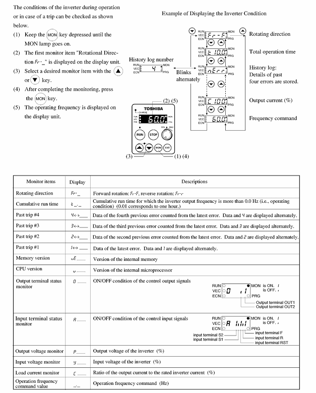
(2) Menu Structure
The panel menu is divided into three levels of structure, with clear logic and easy operation:
First level menu: Monitoring mode (displaying operational data), Parameter mode (setting parameters), Fault mode (viewing fault records), Help mode (operating guide);
Secondary menu: In parameter mode, it is divided into basic parameters (P00-P09), extended parameters (P10-P29), communication parameters (P20-P23), and fault parameters (P30-P39);
Third level menu: specific parameter items (such as P03.01=acceleration time 1).
2. Basic operation process (taking panel control as an example)
(1) Power on and standby
Close the input side circuit breaker (MCCB), power on the inverter, display the Toshiba logo on the screen, and enter the standby interface after about 3 seconds (display "0.0Hz", POWER indicator light on);
Check that there are no fault prompts on the panel (ALARM indicator light off), and confirm that the motor wiring is correct and there is no jamming.
(2) Frequency setting and startup
Press the "MODE" button to switch to the "Panel Control" mode (RUN indicator light flashes);
Rotate the parameter knob to set the target frequency (such as 50Hz), and the display screen will show the set value in real-time;
Press the "RUN" button, the RUN indicator light stays on, the frequency converter accelerates to the target frequency according to the acceleration time (P03.01), and the motor starts;
During operation, the frequency can be fine tuned through the parameter knob (range 0.0-400.0Hz), and no confirmation is required after adjustment, which takes effect in real time.
(3) Shutdown operation
Normal shutdown: Press the "STOP" button, the frequency converter decelerates and shuts down according to the deceleration time (P03.02), the RUN indicator light goes out, and the standby interface is restored;
Emergency stop: Press the external emergency stop button (DI7 terminal), and the frequency converter immediately executes the emergency stop mode (parameter P06.03 set, default deceleration stop). The ALARM indicator light flashes, and the emergency stop button needs to be reset before pressing the "RESET" button to restore.
(4) Fault detection and reset
When a fault occurs, the display screen shows a fault code (such as "OC1"), the ALARM indicator light stays on, and the frequency converter shuts down;
Press the "MODE" button to switch to fault mode, where you can view the cause of the fault and the current/voltage/frequency data at the time of the fault;
After troubleshooting, press and hold the "RESET" button or the "STOP" button for 2 seconds to reset the fault and restore standby mode.
3. External control and communication control operations
(1) External control (terminal control)
Parameter settings: P05.01=1 (external control mode), P06.01=0 (leakage type input);
Wiring: DI1 connected to forward switch, DI2 connected to reverse switch, AI1 connected to 0-10V frequency potentiometer;
Operation: Close the forward switch and start the motor according to the frequency command input by AI1; Disconnect the switch and the motor will slow down and stop.
(2) Communication Control (MODBUS-RTU)
Parameter settings: P05.01=2 (communication control mode), P20.01=3 (9600bps), P20.02=1 (slave address 1);
Upper computer configuration: Set MODBUS-RTU protocol and register address (such as frequency instruction register 0x0001);
Operation: The upper computer sends frequency commands (such as 50Hz corresponding to a value of 5000) and start commands, and the frequency converter performs the corresponding operations; The upper computer can read real-time operating data (such as current register 0x0002).
Core functions and parameter configuration
1. Control mode selection and configuration
The TOSBERT S7 series supports three core control modes, which can be flexibly selected according to the load type:
Control Mode Parameter Code (P01.01) Core Features Applicable Scenarios Key Configuration Parameters
V/f control has a simple structure, high stability, and is compatible with all asynchronous motors; Support linear/square/V/f custom curve fans, pumps, and ordinary conveyors (variable torque/constant torque load) P01.02 (V/f curve type), P01.03 (torque boost)
Sensorless Vector Control (SVC) 1 does not require an encoder and outputs 150% of the rated torque at 0.5Hz; Speed accuracy ± 0.1% for machine tools, cranes, and packaging machines (high-precision, high torque starting) P01.04 (vector control gain), P04.01 (torque limit)
Sensor Vector Control (FVC) 2 requires an external encoder with a speed accuracy of ± 0.01%; Support zero speed torque holding elevators, elevators, precision machine tools (ultra-high precision speed regulation, positioning) P02.01 (encoder type), P02.02 (encoder resolution), P04.08 (zero speed holding enabled)
2. Torque control function (parameter P04 group)
(1) Core torque parameters
Parameter Code Parameter Name Adjustment Range Default Value Function Description
P04.01 Positive torque limit 0.0-200.0% 150.0% Limit the maximum torque of the motor during forward operation to prevent overload
P04.02 Reverse torque limit 0.0-200.0% 150.0% Limit the maximum torque of the motor during reverse operation
P04.05 Torque control enable 0=disabled, 1=enabled 0. After enabling, the frequency converter runs according to the torque command (AI2 input)
P04.08 Zero speed torque holding enable 0=disabled, 1=enabled 0 FVC mode, maintains set torque at 0Hz (default 150%)
P04.09 Zero speed torque holding value 0.0-200.0% 150.0% The magnitude of the torque held at zero speed
(2) Application scenario configuration example (crane hovering)
Control mode: P01.01=2 (FVC mode);
Encoder configuration: P02.01=0 (incremental), P02.02=1024 (encoder resolution);
Torque settings: P04.08=1 (enable zero speed hold), P04.09=120.0% (maintain 120% rated torque);
Effect: After the crane lifts a heavy object, the frequency converter runs at zero speed to maintain torque and prevent the object from falling.
3. Multi speed operation and jog control (parameter P08 group)
(1) Multi speed operation (16 speed)
Principle: Select 16 preset speeds (S1-S16) through the on-off combination of DI3-DI6 terminals;
Parameter configuration: P08.01 (S1 speed) - P08.16 (S16 speed), range 0.0-400.0Hz;
Wiring: DI3=S1, DI4=S2, DI5=S3, DI6=S4, achieve 16 speed through combination (such as DI3=ON → S1, DI3+DI4=ON → S2).
(2) Jog control
Parameter configuration: P08.17 (jog speed)=5.0-50.0Hz (default 10Hz), P08.18 (jog acceleration time)=0.1-10.0 seconds (default 1 second);
Operation: Close DI5 (jog terminal), and the motor runs at jog speed; Disconnect the terminal and the motor will immediately stop (with a default jog deceleration time of 0.5 seconds).
4. Brake control function (parameter P09 group)
The TOSBERT S7 series supports both DC injection braking and regenerative braking, adapting to different braking requirements:
Hardware requirements for configuration of braking mode applicable scenario parameters
DC injection braking precise positioning, short distance braking (such as packaging machine positioning) P09.01=1 (enabled), P09.02=0-10Hz (braking start frequency), P09.03=0-30% (braking voltage), P09.04=0.1-10.0 seconds (braking time) No additional hardware required, built-in braking circuit
Regenerative braking inertia load, long-distance braking (such as centrifuge, elevator descent) P09.10=1 (enabled), P09.11=0-100% (braking torque), P09.12=0.1-10.0 seconds (braking time) Power ≤ 15kW: built-in braking resistor; Power>15kW: External braking unit+braking resistor
5. Energy saving function configuration (parameter P15 group)
(1) Fan/pump specific energy-saving mode
Parameters: P15.01=1 (enabled), P15.02=1 (square torque curve);
Principle: Based on the load characteristics of the fan/pump (load torque is proportional to the square of the speed), dynamically adjust the output voltage and frequency, saving 5-15% energy compared to ordinary V/f mode;
Applicable to variable torque loads such as centrifugal fans, centrifugal pumps, and deep well pumps.
(2) Automatic sleep/wake function
Parameters: P15.05=1 (enabled), P15.06=5.0Hz (sleep frequency threshold), P15.07=10 seconds (sleep delay time), P15.08=10.0Hz (wake-up frequency threshold);
Principle: If the motor operates at a frequency below 5.0Hz for 10 seconds, the frequency converter will shut down and enter sleep mode; When the load increases and the frequency command exceeds 10.0Hz, it will automatically wake up and run to avoid ineffective energy consumption.
6. Protection function configuration (parameter P06 group)
The frequency converter has built-in comprehensive protection functions, which can adjust the protection threshold through parameters to adapt to different device requirements:
Function description of default value adjustment range for protection type parameter code
Overcurrent protection P06.16: When the current exceeds the threshold of 100-200% and 150%, the frequency converter shuts down to protect the power module
Overload protection P06.00 50-150% 110%. If the motor overload time exceeds the set value (according to the inverse time characteristic), the frequency converter will shut down
Overvoltage protection P06.04: When the DC bus voltage exceeds the threshold of 100-120% and 110%, the frequency converter will downshift or shut down
Overheating protection P06.05: When the temperature of the power module exceeds the threshold of 80-100 ℃ and 95 ℃, the frequency converter will downshift or shut down
Grounding protection P06.06 0=disabled, 1=enabled 1. When the grounding current exceeds the threshold (≈ 50mA), the frequency converter shuts down
Troubleshooting and Solutions
1. Classification of fault codes and core troubleshooting logic
Inverter faults are divided into "serious faults" (requiring power-off reset, such as OC2, OH1) and "ordinary faults" (panel reset, such as OV2, ALM1). The troubleshooting follows the logic of "hardware first, parameters later, simple first, complex later":
(1) Detailed explanation of common fault codes
Fault code, fault name, fault cause, troubleshooting steps, and solution
OC1 acceleration overcurrent 1. The acceleration time is too short; 2. Motor winding short circuit; 3. Excessive load; 4. Power module fault 1. Check the acceleration time parameter (P03.01); 2. Use a megohmmeter to measure the insulation of the motor (≥ 500M Ω); 3. Check if the load is stuck; 4. Measure the conductivity of the power module. 1. Increase P03.01 (such as changing from 1 second to 5 seconds); 2. Repair or replace the motor; 3. Clean up foreign objects from the load and reduce the load; 4. Contact after-sales service to replace the power module
OH1 power module overheating 1. Cooling fan failure; 2. Insufficient ventilation gap; 3. The ambient temperature is too high; 4. The fan filter is clogged. 1. Check if the fan is rotating and if there is any abnormal noise; 2. Measure whether the installation gap meets the requirements; 3. Measure the ambient temperature; 4. Check the dust on the fan filter. 1. Replace the fan (model FS-1238); 2. Adjust the installation spacing to the standard value; 3. Install air conditioning or cooling fans; 4. Clean the dust from the filter screen
OV1 DC bus overvoltage: 1. The grid voltage is too high; 2. The deceleration time is too short; 3. Excessive regenerative energy; 4. Open circuit of braking resistor 1. Measure the grid voltage with a multimeter (within ± 10% of the rated voltage); 2. Check the deceleration time parameter (P03.02); 3. Check if the load is an inertial load; 4. Measure the resistance of the braking resistor. 1. Install a grid voltage regulator; 2. Increase P03.02 (such as changing from 2 seconds to 10 seconds); 3. External braking unit; 4. Replace the brake resistor
GF grounding fault 1. Motor grounding short circuit; 2. The output cable of the frequency converter is damaged; 3. Internal grounding of the frequency converter; 4. Excessive grounding resistance. 1. Measure the insulation resistance between the motor winding and the grounding; 2. Check if the outer sheath of the output cable is damaged; 3. Disconnect the motor and measure the insulation output of the frequency converter separately; 4. Measure the grounding resistance. 1. Repair the motor winding; 2. Replace damaged cables; 3. Contact after-sales service for frequency converter maintenance; 4. Rectify the grounding system (grounding resistance ≤ 10 Ω)
Err12 communication fault: 1. Communication cable disconnected; 2. Baud rate mismatch; 3. The address of the slave station is incorrect; 4. Communication interference: 1. Check the RS485 cable connection; 2. Verify the baud rate of the master and slave stations (P20.01); 3. Verify the address of the slave station (P20.02); 4. Check the grounding condition of the shielding layer. 1. Reconnect or replace the communication cable; 2. Unified master-slave station baud rate (such as 9600bps); 3. Correct the slave address (if set to 1); 4. Ensure that the shielding layer is grounded at one end and kept away from the main circuit cables
ALM1 overload alarm: 1. Excessive motor load; 2. The overload protection threshold is too low; 3. Motor stalling: 1. Check the operating current (whether it exceeds the rated current); 2. Check the P06.00 parameter; 3. Check if the motor is stuck. 1. Reduce the load; 2. Increase P06.00 (such as changing from 110% to 120%); 3. Clean up foreign objects from the load and repair the motor
(2) Fault reset method
Common faults (such as ALM1, Err12): After troubleshooting, press the "RESET" button on the panel or long press the "STOP" button for 2 seconds;
Serious faults (such as OC2, OH1): After troubleshooting, disconnect the input side circuit breaker, wait for 5 minutes (capacitor discharge), and then close and energize;
Unable to reset faults (such as EEP1, CPU1): This is an internal hardware fault and requires contact with Toshiba after-sales service for maintenance.
2. Troubleshooting without fault codes but running abnormally
In some scenarios, the frequency converter has no fault codes, but runs abnormally (such as unstable speed and insufficient torque), and needs to be investigated from the following aspects:
Unstable speed: 1 Check whether the analog input signal fluctuates (measure AI1 voltage with a multimeter); 2. Check if the vector control gain (P01.04) is too large; 3. Check if the motor bearings are worn;
Insufficient torque: 1 Check if the torque limit parameter (P04.01) is too low; 2. Confirm whether the control mode is SVC/FVC (with low torque in V/f mode); 3. Check if the grid voltage is too low (affecting output torque);
The frequency cannot reach the set value: 1 Check if the upper limit frequency (P03.05) is lower than the set value; 2. Check if the overload protection is about to trigger (current approaching threshold); 3. Check if the frequency limit function is enabled (P15.09).
Maintenance and lifespan management
1. Maintenance cycle and core maintenance projects
The maintenance of frequency converters is divided into two categories: "regular inspection" and "regular replacement", and the cycle is adjusted according to the operating environment and load rate:
(1) Regular inspection (by cycle)
Maintenance cycle maintenance project maintenance method judgment criteria
Monthly visual inspection of the inverter casing, terminals, and cables for any damage, oxidation, or looseness
Monthly operation data records include operating frequency, current, voltage, module temperature, current ≤ rated current, temperature ≤ 85 ℃
Tighten the main circuit and control circuit terminals with a screwdriver every 6 months without loosening the screws (torque values: M4=2.5N · m, M5=4.0N · m)
Clean the cooling system every 6 months with compressed air (below 0.3MPa) to remove dust from the cooling fan and fins. There is no obvious dust accumulation, and the fan rotates normally
Disconnect the power supply for insulation testing every year, and use a 500V megohmmeter to measure the insulation of the main circuit. The insulation of the main circuit to ground should be ≥ 10M Ω, and the insulation of the control circuit should be ≥ 100M Ω
Every 2 years, the capacitance measurement of the DC bus capacitor shows a capacity decay of ≤ 20% (if exceeded, replacement is required)
(2) Regularly replace components (life management)
The core components of the frequency converter have a clear service life and need to be replaced upon expiration:
Component Name Service Life Replacement Standard Recommended Model
Cooling fan operates continuously for 2-3 years with abnormal noise, decreased speed, and no rotation. Toshiba FS-1238, FS-9225
DC bus capacitor with 5-8 years (ambient temperature ≤ 40 ℃) capacity decay>20%, leakage, bulging Toshiba EEU-FR1C102, EEU-FR1C222
Braking resistor: 3-5 years (frequent braking scenario), resistance change>10%, surface carbonization matching according to model (e.g. BR-10 Ω/500W for 15kW model)
The filter screen is severely clogged for 6-12 months, affecting ventilation. Toshiba filter screen FS-FILTER-01
2. Long term shutdown and restart maintenance
Long term shutdown maintenance (≥ 6 months):
Before shutdown: Backup the parameters of the frequency converter (through the panel or software) and clean the internal dust;
Storage period: Power on every 6 months (no load, voltage gradually increases from 0 to rated value for 30 minutes) to activate the capacitor;
Storage environment: Temperature -20 ℃~40 ℃, humidity ≤ 60% RH, no corrosive gases.
Restart maintenance:
Check if the appearance, terminals, and cables of the frequency converter are normal;
Measure the insulation resistance of the main circuit;
Restore backup parameters, conduct a 5-minute no-load trial run, check for any abnormalities, and then run with load.
- OMRON
- ABB
- General Electric
- EMERSON
- Honeywell
- HIMA
- ALSTOM
- Rolls-Royce
- MOTOROLA
- Rockwell
- Siemens
- Woodward
- YOKOGAWA
- FOXBORO
- KOLLMORGEN
- MOOG
- KB
- YAMAHA
- BENDER
- TEKTRONIX
- Westinghouse
- AMAT
- AB
- XYCOM
- Yaskawa
- B&R
- Schneider
- KONGSBERG
- NI
- WATLOW
- ProSoft
- SEW
- ADVANCED
- Reliance
- TRICONEX
- METSO
- MAN
- Advantest
- STUDER
- DANAHER MOTION
- Bently
- Galil
- EATON
- MOLEX
- DEIF
- B&W
- ZYGO
- Aerotech
- DANFOSS
- Beijer
- Moxa
- Rexroth
- Johnson
- WAGO
- TOSHIBA
- BMCM
- SMC
- HITACHI
- HIRSCHMANN
- Application field
- XP POWER
- CTI
- TRICON
- STOBER
- Thinklogical
- Horner Automation
- Meggitt
- Fanuc
- Baldor
- SHINKAWA
- Other Brands
- UniOP
- KUKA
- Iba
- Beckhoff
-
 Basler BE1-25 Time Overcurrent Relay M1FA6PA4S0F
 -
 Basler SR4A2B05B3E Static Voltage Regulator
 -
 Basler DECS-200-2L Digital Excitation Control
 -
 Basler BE303280001 Control Transformer
 -
 Basler 9262103004 Voltage Regulator Board For Basler DECS-400
 -
 Basler ICRM-7 Inrush Current Reduction Module
 -
 Basler BE1-32R Power Relay
 -
 BASLER ELECTRIC KR4F VOLTAGE REGULATOR 9042600100 600V 50/60Hz
 -
 Basler 9222600101 Power Module
 -
 Basler SR8A-2B15B3A Static Voltage Regulator
 -
 BASLER BE1-87G G1E A1L A0N1P Generator Differential Relay w/ Reactor 9170818100
 -
Basler 9284900101 DECS Power Module
-
 Basler PRS250 Veri-Sync Relay
 -
 Basler BE 12296 001 Transformer
 -
 Basler 905970-104 Rev.M Voltage Regulator
 -
Basler BE1-87T Transformer Differential Relay
-
 Basler SR8A-2B15B3A Static Voltage Regulator
 -
 Basler SR32A2B05B3E Static Voltage Regulator
 -
 Basler SR4A-2B16B3A Static Voltage Regulator
 -
 Basler SR32A-2B13B3E Static Voltage Regulator
 -
 Basler KR4F Voltage Regulator 9042600100
 -
 Basler SSR 32-12 Static Voltage Regulator 400Hz
 -
 Basler CBS 212A Current Boost System
 -
 Basler MVC236 Manual Control Module
 -
Basler UFOV Protective Module 9040000100
-
 Basler SSR 125-12 Static Voltage Regulator
 -
 Basler SR4A2B10A3E Static Voltage Regulator
 -
 Basler BE1-25 Solid State Time Overcurrent Relay
 -
 Basler MVC 232 Manual Voltage Control Module
 -
Basler PRS 250 Veri-Sync Relay
-
 Basler UFOV 260A Under Frequency Over Voltage Relay
 -
 Basler RUL2098-10GC Load Relay
 -
 Basler 9 1049 04 100 PC Board
 -
Basler 125-12 Static Voltage Regulator
-
Basler PRS 250 Veri-Sync Relay
-
Basler 9185900102 SSR 125-12 Regulator
-
Basler BE12819001 Reactor
-
 Teradyne 535-100-00 Power Supply
 -
 Basler BE1-67 Directional OC Relay
 -
 Basler PRP110 Reverse Power Relay
 -
 Basler BE30631001 Isolation Transformer
 -
 Basler DECS-200-2L Digital Excitation Control
 -
 Basler BE1-47N Voltage Phase Sequence Relay
 -
 Basler AEC63-7 Analog Excitation Controller 220-277V
 -
Basler BE1-50/51B-107 Overcurrent Relay
-
 Basler Electric BE1‑32R BE1‑E1P‑BON0F Protective Relay
 -
Basler BE1-25 Solid State Time Overcurrent Relay M1EA6PA5S1F
-
 Basler MVC 232 Manual Voltage Control Module 90 37000 103 60VAC 55VDC
 -
Basler RAL6144-16GM Racer GigE Line Scan Camera
-
Basler SSR 63-12 Static Voltage Regulator
-
 Basler BE1-51A Overcurrent Relay
 -
Basler BE1-87T Solid State Protective Relay
-
Basler SR4A2B01B3A Static Voltage Regulator
-
 Basler SSR 32-12 Static Voltage Regulator
 -
 Basler TRR00696 Transformer 1KVA 115V
 -
 Basler DECS-100-B15 AVR Replacement
 -
Basler BE1-27 Under-Voltage Relay
-
 Basler ACA2000-50GM Interface Module
 -
 Basler AEC63-7 Analog Excitation Controller
 -
Basler PRS 250 Veri-Sync Relay
-
 Basler SR4A-2B15B3A Static Voltage Regulator
 -
Basler BE1-32R Power Relay
-
Basler SR8A-2B06B3E Static Voltage Regulator
-
Basler BE1-81 O/U Frequency Relay
-
 Basler BE1-51A-K2E-W6M-B1N0F Overcurrent Relay
 -
Basler BE1-851 Overcurrent Relay G3A1S1 – 48-125V AC/DC
-
 Basler BEI-51 Overcurrent Relay – NSN 5945-01-293-2363
 -
Basler Electric L301KC Protective Relay – L301KC
-
 Basler DECS-100-B15 Automatic Voltage Regulator – Generator AVR
 -
Basler SR4A-2B15B3A Static Voltage Regulator – SR4A2B15B3A
-
Basler UF 312 Under Frequency Protective Module – 9094700100
-
Basler Electric MVC 232 Manual Control Module – 60VAC 55VDC 20A
-
Basler PRS 250 Veri-Sync Relay – Generator Synchronizing Relay
-
 Basler DECS-100-A05 Digital Regulator Review
 -
 Basler AEM-2020 Analog Expansion Module Specs
 -
 Basler DECS-100-B15 Digital Excitation Specs
 -
Basler Electric 9125600106 Regulator Component
-
Basler BE1-51A-K1E-W6M-B1N0F Overcurrent Relay
-
 Basler MVC-301 MVC 300 Excitation Controller
 -
Basler SSR 32-12 Static Voltage Regulator
-
Basler 9-2849-00-101 Control Module
-
Basler BE1-51A Overcurrent Relay
-
 Basler BE1-51/27R Overcurrent Relay
 -
 Basler BE1-51 Overcurrent Relay
 -
 Basler SR8A-2B15B3A Static Voltage Regulator
 -
 Basler BE32965001 Transformer and Timer Board
 -
 Basler 9174700100 EL200-7 Excitation Limiter
 -
 Basler BE2000E AVR Voltage Regulator
 -
Basler BE1-87G Differential Relay
-
 Basler BE21834001 Generator Control Module
 -
Basler DECS-100-B15 AVR
-
 Basler D90 96801 100 PCB Card
 -
 Basler XR2002F Voltage Regulator (110 VAC, 48-480 Hz)
 -
 Basler SR8A-2B14B3A Regulator
 -
 Basler 9561500100 Module
 -
 Basler DECS-400 BE1-11 System
 -
 Basler DECS-100-B15 Excitation Control
 -
Basler SCP 210 Frequency Controller
-
Basler SR4A-2B15B3A Static Voltage Regulator
-
Basler BE1-32R Power Relay
-
 Basler PIA2400-17GM Power Interface Adapter
 -
 Basler MVC 232 Manual Voltage Control Module
 -
Basler SSR 32-12 Static Voltage Regulator
-
Basler 5MW AVR Generator Voltage Regulator
-
 Basler VR63-4B Voltage Regulator
 -
Basler DECS-100-A05 AVR for Engine Generator
-
Basler DECS-100-B15 Automatic Voltage Regulator
-
Basler BE1-32R Directional Power Relay
-
Basler BE1-87B Differential Relay
-
 Basler UFOV 260A Protective Module
 -
 Basler 9-2614-02-100 PCB Rev M
 -
Basler DECS-100-B15 Digital AVR
-
 Basler 9284900103 PS DECS-400N
 -
 Basler D4N3H1U Intertie Protection
 -
 Basler DECS-100-B15 A15 AVR
 -
 Basler KR4F Voltage Regulator
 -
 Basler BE26434 T14 Transformer
 -
 Basler SR8A-2B15B3A Regulator
 -
 Westinghouse 774B472A12 AR Relay
 -
Basler DECS-100-B15 AVR
-
Basler XR2002F Regulator 110V
-
Basler SR125-E Static Regulator
-
Basler SSR 125-12 Regulator
-
Basler MOC2599 Motor Pot
-
 Basler BE1-DFPR Feeder Relay
 -
 Basler CBS 305 Current Boost
 -
Basler BE1-25 AutoSync
-
Basler MVC 300 Voltage Control


